


Special offers from our partners!

Find Replacement BBQ Parts for 20,308 Models. Repair your BBQ today.
8
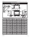
LDVR Series Direct Vent Gas Fireplace
10007317
Installation
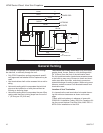
1. Thread the wiring through the holes on the end
panels of the fireplace. Take care not to cut the wire
or insulation on metal edges. Route the wire to a
conveniently located receptacle box.
2. Attach the wire to the ON/OFF switch and install the
switch into the receptacle box.
3. Connect the other ends of the wire to the gas control
valve. (Fig. 6)
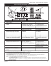
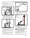
The gas pipeline can be brought in through the rear
of the appliance as well as the bottom. Knockouts are
provided on the bottom behind the valve to allow for the
gas pipe installation and testing of any gas connection.
It is most convenient to bring the gas line in from the
rear right side of the valve as this allows fan installation
or removal without disconnecting the gas line.
The gas line connection can be made with properly
tinned 3/8” copper tubing, 3/8” rigid pipe or an ap-
proved flex connector. Since some municipalities have
additional local codes, it is always best to consult your
local authority and the National Fuel Gas Code, ANSI
Z223.1/NFPA 54 in the USA or the CSA-B149.1 installa-
tion code.
Do not wire the remote ON/OFF wall switch
for the gas fireplace to the 120 volt power
supply.
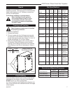
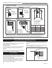
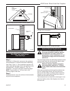
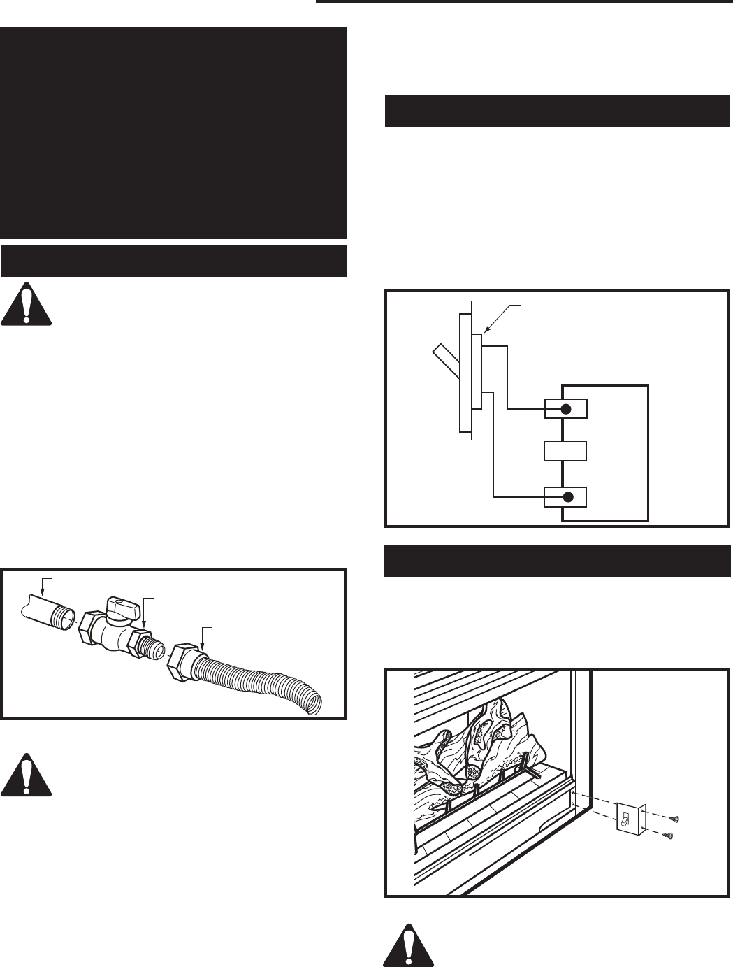
Alternate Switch Location
The remote switch can be installed on the front/side
of the access door. Simply mount the switch to the
bracket provided and screw the bracket to either side
of the frame, lining up the screws with the pre-punched
holes. (Fig. 7)
The gas control is equipped with a captured screw type
pressure test point, therefore it is not necessary to pro-
vide a 1/8” test point up stream of the control.
When using copper or flex connector use only approved
fittings. Always provide a union when using black iron
pipe so the gas line can be easily disconnected for
burner or fan servicing. See gas specification for pres-
sure details and ratings.
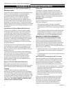
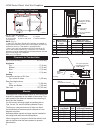
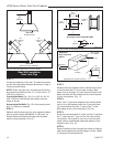
Gas Line Installation
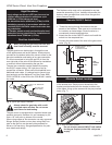
Remote ON/OFF Switch
When purging the gas lines, the front win-
dow frame assembly must be removed.
Always check for gas leaks with a mild
soap and water solution. Do not use an
open flame for leak testing.
FP297A
INSTA VENT FREE
UVHB26 GAS SUPPLY
7/1/98
FP297A
1/2” Gas Supply
1/2” NPT x 1/2” Flare Shut-
off Valve
3/8” Flex Line
(From Valve)
Fig. 5 Typical gas supply installation.
FP1024
alternate
remote switch
location
1/27/00 djt
FP1024
Fig. 7 Alternate switch location.
High Elevations
Input ratings are shown in BTU per hour and are
certified without deration for elevations up to
4,500 feet (1,370m) above sea level.
For elevations above 4,500 feet (1,370m) in USA,
installations must be in accordance with the cur-
rent ANSI Z223.1/NFPA 54 and/or local codes hav-
ing jurisdiction.
In Canada, please consult provincial and/or local
authorities having jurisdiction for installations at
elevations above 4,500 feet (1,370m).
TP
TH
TP
TH
FP1224
Remote switch
11/02
Remote ON/OFF Switch
or Thermostat
or Remote Control
Gas
Control
Valve
FP1224
Fig. 6 Remote switch wiring diagram.
The fireplace valve must not be subjected to any test
pressures exceeding 1/2 psi. Isolate or disconnect this
and any other gas appliance control from the gas line
when pressure testing.