


Special offers from our partners!

Find Replacement BBQ Parts for 20,308 Models. Repair your BBQ today.

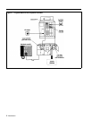
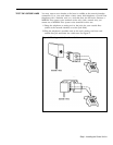
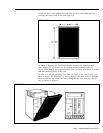
The 2-line adapter has two jacks, each of which carries a single-pair line from
the 2-line network interface jack. The 50-pin connector (attached to a 66-type
block) carries up to 25 lines. You can connect your outside telephone lines
from these (or other) network interface connectors to the control unit in many
ways. The method you use to connect your outside telephone lines to the
control unit depends on the type of network interface the local telephone
company installs at the control unit location. The table on the next page tells
you what to do next depending on the type of network interface you have.
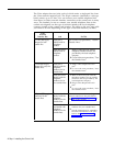
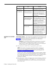
If the
Network
Interface Has
A 1-line (RJ11-type)
adapter for each
outside line
A
2-line (RJ14-type)
adapter for every two
outside lines
A
50-pin (RJ21-type)
connector for the
outside lines
And
Each jack is
labeled with its
telephone
number
Each jack is not
labeled with its
telephone
number
Each jack is
labeled with the
telephone
numbers for its
outside lines
Each jack is not
labeled with the
telephone
numbers for its
two outside lines
The interface is
labeled with the
telephone
numbers for the
outside lines
The interface is
not labeled with
telephone
numbers for the
outside lines
Do This
Go on to the next procedure, "Test the
Outside Lines."
1
Mark or label each jack with its
telephone number from the list
provided by the local telephone
company.
2
Go on to the next procedure, "Test
the Outside Lines."
1
Plug
a 2-line adapter into each
jack.
2
Go on to the next procedure, "Test
the Outside Lines."
1
Mark or label each jack with the
telephone numbers for its outside
lines from the list provided by the
local telephone company.
2
Plug a 2-line adapter into each
jack.
3
Go on to the next procedure, "Test
the Outside Lines."
See the instructions for extending the
network interface to the jack field in
the "Jack Field Wiring Supplement" at
the end of this manual.
1
Mark or label the interface with the
numbers for your outside lines.
2
See the instructions for extending
the network interface to the jack
field in the "Jack Field Wiring
Supplement" at the end of this
manual.
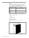
4
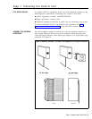
Step 1: installing the Control Unit