


Special offers from our partners!

Find Replacement BBQ Parts for 20,308 Models. Repair your BBQ today.

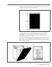
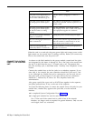
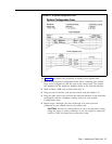
FIGURE 14 A System Configuration Form.
1
2
3
4
5
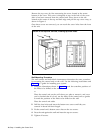
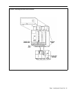
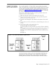
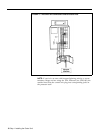
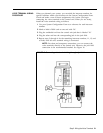
See Figure 15 and follow this procedure to connect your outside lines:
Refer to your System Configuration Form when connecting the outside
lines you’ve assigned to each line jack on the control unit. The outside
line numbers are the telephone numbers listed at the network interface.
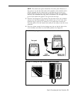
Mark or label a D2R cord on both ends with "A."
Plug one end of the line cord into the control unit jack labeled "A."
Plug the other end of the cord into the network interface or jack field that
corresponds with the telephone number shown on your System
Configuration form.
Repeat steps 2 through 4 for lines B through H or until you have
connected all your outside lines to the control unit.
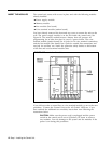
CAUTION: Do not run cords inside or on top of air plenums or ducts,
along hot pipes, or across walkways. If you use staples to attach the
cords to a wall, be careful not to pierce the cords.
Step 1: Installing the Control Unit
17