


Special offers from our partners!

Find Replacement BBQ Parts for 20,308 Models. Repair your BBQ today.

5
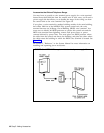
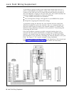
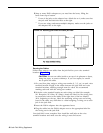
Snap as many Z601A adapters as you need into the boxes, filling the
boxes from top to bottom.
—
If one of the jacks on the adapter has a black dot on it, make sure that
the jack with the black dot faces to the right.
—
If you are using cutdown-to-modjack adapters, make sure the jacks on
the adapters face to the right.
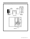
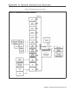
FIGURE 39 Attaching jack boxes to create a jack field.
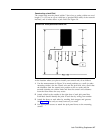
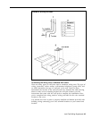
Running the Cables
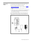
Follow these steps to run cables from the jack field to your voice terminal
locations (Figure 40).
CAUTION: Do not run cables inside or on top of air plenums or ducts,
along hot pipes, or across walkways. If you use staples, be careful
not to pierce the cable.
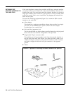
1 On your floor plan, assign a wiring run number (1, 2, 3, etc.) to each voice
terminal location. Rough in the cables between the jack field and voice
terminal locations, allowing enough room for slack. We recommend
marking each end with the wiring run number.
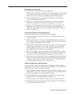
2 Write the voice terminal location on each wiring run label (for example,
❑ 1 Reception, ❑ 2 Sales, ❑ 3 Shop). Attach the label for the wiring runs
in consecutive order to the inside of the right door of the box labeled
❑ 16, beginning at the top. Label the remaining wiring runs and wiring
boxes in the same way until there is a label assigning a wiring run to each
jack in the jack field.
3
Insert the Z601A adapters into the apparatus boxes.
4
Plug the cables into the Z601A adapter next to the appropriate label for
the wiring run in the jack field.
Your jack field is now complete. Now install the wall jacks at the voice
terminal locations and make sure the wiring is neat and secure.
48
Jack Field Wiring Supplement