


Special offers from our partners!

Find Replacement BBQ Parts for 20,308 Models. Repair your BBQ today.

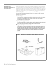
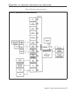
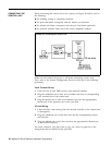
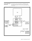
CONNECTING THE
Before connecting the control unit to the system, see Figure 45 and be sure of
CONTROL UNIT
the following:
● The building wiring is completely installed.
● The jack field labels correspond with the distant end locations.
● The distant end labels correspond with the jack field labels (optional).
● The network interface labels have the correct telephone numbers.
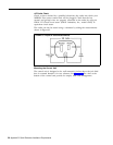
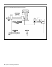
FIGURE 45 Connecting the control unit.
Make sure the control unit power is off before connecting system wires.
Then, refer to the System Configuration Form for each step in the following
procedures.
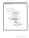
Voice Terminal Wiring
1
Label one end of each D8W cord for each intercom number.
2
3
Plug the unlabeled end of each voice terminal cord into its corresponding
voice terminal jack of the control unit.
Plug the labeled end of each voice terminal cord into the appropriately
labeled jack in the apparatus box of the jack field.
CO Line Wiring
1
2
3
Label each line cord running from the network interface to the control unit
(A through H).
Plug the unlabeled end of each line cord into the corresponding control
unit line jack.
Plug the labeled end of each line cord into the appropriately labeled jack
at the network interface.
For future reference, you may want to copy on a sheet of paper all of the
assignments that are labeled at the jack field.
60
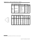
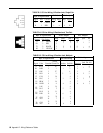
Appendix B: Quick Reference Installation Requirements