


Special offers from our partners!

Find Replacement BBQ Parts for 20,308 Models. Repair your BBQ today.

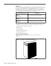
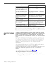
If
The green power light doesn’t go
on and the orange light on the
power switch also doesn’t go on
The green power light is on, but
the orange power switch light is
off .
The green power light is off but
the orange power switch light is
on and the outlet is working
properly
The red warning light continually
flashes or remains lit
The red warning light continues to
flash or remains lit
If the red warning light still
continually flashes or remains lit
Then
Test the outlet by plugging in a radio or a
lamp.
The outlet is not functioning, is miswired or
improperly grounded. Have it repaired or use
another outlet.
Stop the installation. Turn off the control
unit, unplug it from the ac outlet, and contact
your equipment supplier for assistance.
Unplug the power cord and plug it in again.
Set the power switch to Off, and make sure
that each module is seated firmly in its slot.
Then set the power switch to On.
Stop the installation. Contact your equipment
supplier for assistance.
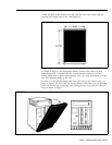
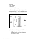
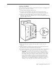
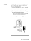
When the unit is on and only the green power light and orange power switch
light remain on, the control unit is working correctly. Before you connect any
lines to the control unit, turn the power off.
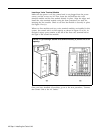
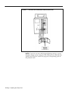
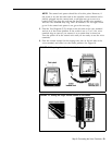
CONNECT THE OUTSIDE
As shown on the label attached to the power module, control unit line jacks
LINES TO THE CONTROL are designated by the letters A through H. The A line jack is the second from
UNIT
the top, B is third from the top, C is fourth, and so on. The topmost line
jack, the Auxiliary jack, is described under "Auxiliary Line Telephone" in this
manual.
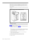
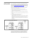
Connect the outside lines to the line jacks in an unbroken sequence. If you
start with A, for example, the next connection should be B, the next C, and
so on. Although any outside line can be connected to any line jack, do not
skip jacks once you have begun. If you start with B, the next connection
should be C, followed by D, and so on. This simplifies future line
administration.
Also, group special line types such as WATS lines together in the sequence,
and place personal lines, if any, at the end of the sequence.
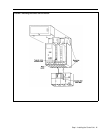
You need the following items to connect the control unit to the jacks for your
outside lines, whether they appear at the jack field, or at the network
interface.
●
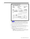
A completed System Configuration Form (Figure 14)
●
A single-pair modular line cord for each outside line
Use a 7-foot cord if the control unit is within 6 feet of the network
interface; use longer cords as required for greater distances. Only use one
cord length; don’t use extensions.
16
Step 1: Installing the Control Unit