


Special offers from our partners!

Find Replacement BBQ Parts for 20,308 Models. Repair your BBQ today.

Index
A
Accessories, 29
adding, 35 – 41
Accessory equipment, 35
Adapter, 4-line, 50, 51
RJ11-type, 3, 4
RJ14-type, 3, 4
Z601A, 45, 48
Adding a voice terminal.
See
Voice terminal, adding
Apparatus box, 50, 60
Auxiliary jack, 16, 29
Auxiliary line, 16
Auxiliary line telephone, line module jack, 29
B
Battery, 12
BIS voice terminals.
See
Voice terminal
C
Cable, 25-pair, 51
Cable stripping tool, 46
Cable termination tool (punch down tool), 46
Cables running, procedures for, 48
Call Report, 20
Changing the system, adding and moving lines, voice
terminals, 42 – 43
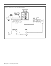
CO line wiring, 60
6-position jack, multipair, 66
6-position jack, single-pair, 66
6-position jack, two-pair, 66
Connect each voice terminal to the system, procedure, 24
Connect the control unit to the ac outlet, 12
Connect the outside lines to the jack field, procedure, 51
Connecting the voice terminals, 22 – 29
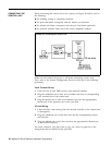
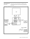
Connectivity overview.
See
System connectivity overview
Connector, 50-pin, 51
RJ21-type, 3, 4
Connector cable, single-ended 25-pair, 50
Constructing a jack field, control unit location, 47
Constructing a jack field, procedure, 47
Constructing and connecting the jack field, 45 – 49
Control unit at full capacity, description of, 14
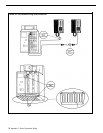
Control unit
connecting, 60
connecting outside lines to, 16 – 18
connecting outside lines to, items required, 16
connecting outside lines to, method, 16
connecting outside lines to, procedure, 17
connecting to ac outlet, 15 – 16
connecting to ac outlet, outlet type, 15
connecting to ac outlet, procedure, 15
environment of, 7
front and top covers, 8
grounding, 6
installing, 3 – 18
location requirements, 6
maximum wiring run, 7
mounting, 6 – 11, 58
mounting hardware, 8
mounting hole access, 8
mounting wall types, 8
D
Data collector, 36
Dial tone test tool, 5
DIW cable, 46, 47
E
Extending the network interface to the jack field, 50 – 52
required items, 50
F
FCC registration and repair information, 53
FCC regulations, notifying local phone company, 3
ringer equivalence number, 3
system registration number, 3
4-Pair wiring, 65
5-Button voice terminal, 22, 71
G
General purpose adapters, 35
Ground, CO line protector tests, 61 – 62
third-wire, 15
Grounding requirements, 15, 61 – 64
I
In-Range, Out-of-Building protectors, 19, 40
In-Range, Out-of-Building voice terminal, 40
Installation requirements, control unit environment, 57
quick reference, 57 – 60
Intercom 10, as attendant location, 19
for system administration, 19
Intercom number, labeling, 27
verification procedure, 27
J
Jack, RJ11-type, 6
RJ14-type, 6
Jack field, 43
adding jacks to, procedure, 51
connect the outside lines to, 51
constructing and connecting, advantages of, 45
constructing, control unit location, 47
construction recommendations, 45
defined, 44
installation, 1
labels, 60
moving voice terminals within, example, 45
wiring supplement, 1, 4, 44 – 52
Jack panel box, 50
labeling, 51
Jack panel boxes.
See
Apparatus boxes
Jacks, labeling, 51
L
Line board.
See
Line module
Line cord, single-pair modular, 16
Line jacks, 16
Line module, 12
inserting, 13
Lines, testing for a dial tone, 30 – 31
Index I-1