


Special offers from our partners!

Find Replacement BBQ Parts for 20,308 Models. Repair your BBQ today.
www.desatech.com
116647-01B 9
INSTALLATION PLANNING
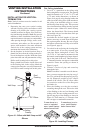
There are two basic types of direct-vent instal-
lation:
• Horizontal Termination
• Vertical Termination
Horizontal Termination Installation
IMPORTANT: Horizontal square terminations
require only inner portion of wall restop. Hori-
zontal installations using round termination require
exterior portion of wall restop (see Figure 14,
page 11).
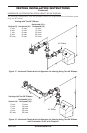
1. Set the replace in its desired location and
determine the route your horizontal venting
will take. Do not secure the replace until
all venting has been installed. Some installa-
tions require sliding the replace in and out
of position to make nal venting connections.
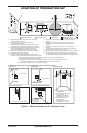
Figures 14 through 18 on pages 11 through 13
show different congurations for venting with
horizontal termination that will help you decide
which application best suits your installation.
Check to see if wall studs or roof rafters are in
the path of your desired venting route. If they
are, you may want to adjust the location of the
replace.
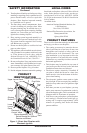
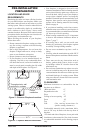
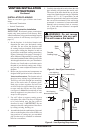
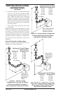
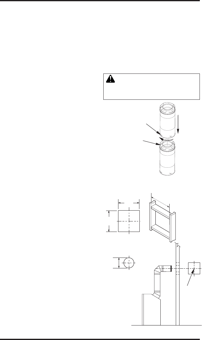
2. Direct vent pipe sections and components are
designed with special twist-lock connections.
Twist-Lock Procedure: The female ends of
the pipes have locking lugs (indentations).
These lugs will slide straight into matching
slots on the male ends of adjacent pipes.
Push pipe sections together and twist one
section clockwise approximately one-quar-
ter turn until the sections are fully locked
(see Figure 8). Note: Horizontal runs of vent
must be supported every three feet. Use wall
straps for this purpose.
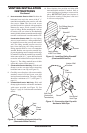
3. Use a 45° elbow to connect venting system
to replace ue collar. The elbow is designed
to be twist-locked onto the flue collar as
described in step 2. IMPORTANT: Do not
attempt to alter the conguration of the elbow
by cutting, twisting, bending, etc.
4. Assemble the desired combination of pipe and
elbows to the replace ue collar. If there are
long portions of venting run, pre-assembled
pipe sections may be installed as subassem-
blies for convenience.
VENTING INSTALLATION
INSTRUCTIONS
Continued
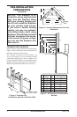
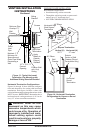
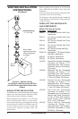
5. Carefully determine the location where the vent
pipe assembly will penetrate the outside wall.
The center of the hole should line up with the
center-line of the horizontal vent pipe. Mark the
wall for a 10
3
/4" x 10
3
/4" square hole. Cut and
frame the square hole in the exterior wall where
the vent will be terminated. If the wall being
penetrated is constructed of noncombustible
material, such as masonry block or concrete,
a 8
1
/2" hole with zero clearance is acceptable
(see Figure 9).
WARNING: Do not recess
vent termination into any wall.
This will cause a re hazard.
Figure 8 - Vent Pipe Connections
Female
Locking Lugs
Male
Slots
(Framing
Detail)
10
3
/
4
"
10
3
/
4
" Inside Framing
10
3
/
4
"
8
1
/
2
"
Vent
O
pening
Combustible Wall
Vent Opening
Noncombustible Wall
Figure 9 - Vent Opening Requirements
Center
of Hole