


Special offers from our partners!

Find Replacement BBQ Parts for 20,308 Models. Repair your BBQ today.

www.desatech.com
116647-01B 19
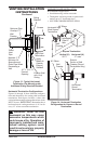
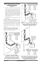
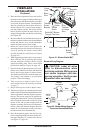
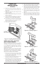
3. Place the blower against the lower rear wall of
the rebox outer wrapper with the exhaust port
directed upward and the thermodisc positioned
up near the replace bottom. The thermodisc
must be oriented near the replace bottom as
shown in Figure 28, in order to sense tempera-
ture and properly operate. The blower will be
held in position against the back wall by the
magnets incorporated onto the blower housing
(see Figure 28).
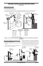
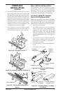
4. Be certain that all wire terminals are securely at-
tached to terminals on blower motor and thermal
switch and that the screw for the thermodisc
bracket and green ground wire is tight.
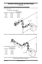
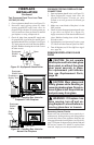
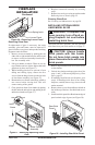
5. Mount the speed control box against the
mounting plate provided in the lower replace
cavity by placing the plastic control shaft
forward through the round hole (see Figure
26, page 18).
6. While supporting speed control, secure control
shaft with lock nut by pushing and turning
lock nut with pliers clockwise until it is tight
against mounting plate. Place control knob
provided on shaft (see Figure 26, page 18).
7. Check to make sure that the power cord is com-
pletely clear of the blower wheel and that there
are no other foreign objects in blower wheel.
Also double check all wire leads and make sure
wire routing is not pinched or in a precarious
position. Correct accordingly.
8. Turn on power to duplex outlet if previ-
ously turned off per the warning in column
2, page 17.
9. Plug in blower power cord to duplex outlet.
10. The blower will only run when the speed control
knob is in the ON position and the thermal switch
senses temperature after the replace begins to
heat up. The blower speed can be adjusted by
rotating the control knob. To turn off, turn knob
fully counterclockwise until it clicks off. If the
blower is ON and has been running with the
replace operating, the blower will continue to
run for a short time after the replace has been
turned off. As the thermal switch cools down,
the blower shuts down automatically.
11. Peel off the backing paper and stick the sup-
plied wiring diagram decal on the rebox bot-
tom approximately 12" in front of the blower
(see Figure 27, page 18).
FIREPLACE
INSTALLATION
Continued
Thermodisc
Figure 28 - Blower Model BKT
Air Flow
Direction
Route BKT Blower
Through This Area
Magnets
Blower
Location
Side View Firebox Bottom
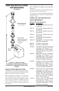
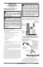
Black
Wire
Phillips
Screw
Blue Wire
Ring
Terminal
on Green
Wire
White Wire
Thermal
Switch
Thermal
Switch
Bracket
Power
Cord
Air Flow
Direction
Magnetic
Strips
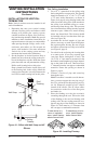
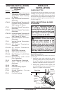
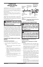
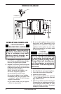
Figure 29 - Blower Wiring Diagram for
Thermostat-Controlled Models
Blower Wiring Diagram
CAUTION: Label all wires
prior to disconnection when
servicing controls. Wiring errors
can cause improper and dan-
gerous operation. Verify proper
operation after servicing.
Blue
Variable
Fan Switch
Fan Switch
(N.O.)
Green
White
On
110/115
V.A.C.
Blower
Motor
Black
Off
1
2
Black