


Special offers from our partners!

Find Replacement BBQ Parts for 20,308 Models. Repair your BBQ today.
www.desatech.com
116647-01B 17
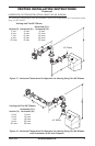
VENTING INSTALLATION
INSTRUCTIONS
Continued
Number Description
HHTK-58 High Wind Round Horizontal
Termination Kit (Includes Round
Termination, Wall Firestop,
45° Elbow)
HHT-58 High Wind Round Termination Kit,
Galvinized
HTK-58 Horizontal Round Termination Kit
(Includes Round Termination,
Wall Firestop, 45° Elbow)
HT-58 Horizontal Round Termination,
Galvanized
HTS-58 Horizontal Square Termination,
Galvanized
HTKS-58 Horizontal Square Termination Kit
(Includes: Square Termination,
Wall Firestop, 45° Elbow)
HTS-58 Horizontal Square Termination,
Galvanized
VT-58 Vertical Round Termination,
Galvanized
ST-58-14 14" Sno rkel Termin ation,
Galvanized
ST-58-36 36" Sno rkel Termin ation,
Galvanized
SC-58 Storm Collar, Galvanized
WF-58 Wall Firestop, Galvanized
RF-58-6 Roof Flashing - 0 to 6/12 Pitch,
Galvanized
RF-58-12 Roof Flashing - 6/12 to 12/12
Pitch, Galvanized
VR-58 Vertical Restrictor, Galvanized
S-58 V i ny l S i d in g S t an d o ff ,
Galvanized
WS-58 Wall Strap
CS-58 Cathedral Ceiling Support
FP-58 Firestop Plate
SF-58 Stucco Flashing - For use
with HTS-58
RF-58 Flat Roof Flashing
FIREPLACE
INSTALLATION
CHECK GAS TYPE
Use proper gas type for the replace unit you are
installing. If your gas supply is not correct, do not
install replace. See retailer where you purchased
the replace for proper replace according to your
gas type or to purchase gas conversion kit (see Ac-
cessories, page 33).
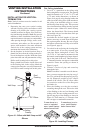
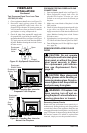
INSTALLING OPTIONAL bLOWER
ACCESSORY
NOTICE: If installing blower in
an existing replace with gas
connections, shut off gas sup-
ply and disconnect heater from
gas supply. Contact a qualied
service person to do this.
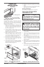
WARNING: If there is a duplex
electrical outlet installed in the
right side of the bottom of the
replace base area, be sure that
the electrical power to the outlet is
turned off before proceeding with
blower installation. Failure to do
this may result in serious injury.
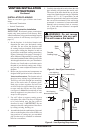
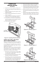
Model BK Installation
Follow all instructions provided in the blower
accessory kit.
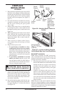
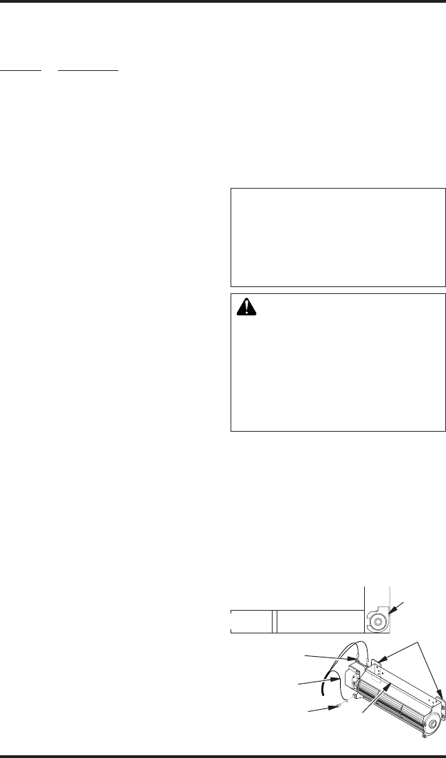
1. Attach the power cord to the blower motor
by rmly pushing the two female terminals at
the end of the power cord onto the two spade
terminals on the blower motor (see Figure 25).
2. Attach green ground wire from power cord
to blower housing using screw provided (see
Figure 25). Tighten screws securely.
Figure 25 - Blower Model BK
Magnetic
Strips
Exhaust
Port
Screw
Green
Ground
Wire
Spade
Terminals
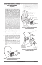
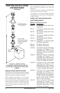
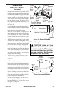
Side View
Lower Firebox
Cavity
Blower
Location