


Special offers from our partners!

Find Replacement BBQ Parts for 20,308 Models. Repair your BBQ today.
www.desatech.com
116647-01B 21
IMPORTANT: Install main gas valve (equipment
shutoff valve) in an accessible location. The main
gas valve is for turning on or shutting off the gas
to the appliance.
Check your building codes for any special re-
quirements for locating equipment shutoff valve
to replaces.
Apply pipe joint sealant lightly to male NPT
threads. This will prevent excess sealant from
going into pipe. Excess sealant in pipe could result
in clogged replace valves.
WARNING: Use pipe joint
sealant that is resistant to liquid
petroleum (LP) gas.
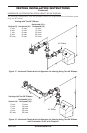
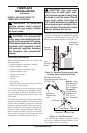
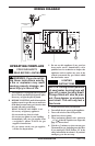
We recommend that you install a sediment
trap/drip leg in supply line as shown in Figure
31, page 20. Locate sediment trap/drip leg where
it is within reach for cleaning. Install in piping
system between fuel supply and replace. Locate
sediment trap/drip leg where trapped matter is not
likely to freeze. A sediment trap traps moisture and
contaminants. This keeps them from going into
replace gas controls. If sediment trap/drip leg is
not installed or is installed wrong, replace may
not run properly.
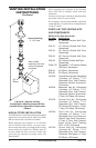
CONNECTING FIREPLACE TO GAS
SUPPLY
Installation Items Needed
• 5/16" hex socket wrench or nut-driver
• sealant (resistant to propane/LP gas, not pro-
vided)
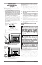
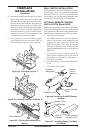
1. Open lower louver door panel by gently
pulling forward.
2. Route exible gas line (provided by in-
staller) from equipment shutoff valve to
replace. Route exible gas supply line
through one of the access holes on side of
replace.
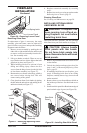
3. Attach exible gas line from gas supply
to control valve (see Figure 32).
4. Check all gas connections for leaks. See
Checking Gas Connections.
FIREPLACE
INSTALLATION
Continued
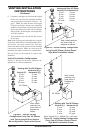
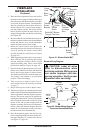
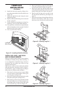
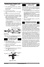
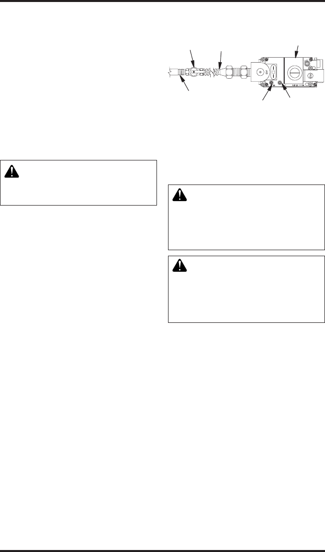
Figure 32 - Connecting Flexible Gas Line
to Electronic Valve
1/2" NPT
Incoming Gas
Line
Inlet
Pressure
Tap
Outlet
Pressure
Tap
Equipment
Shutoff
Valve
Flexible Gas
Line Do NOT
Kink
Note: Wire Connections Not Shown for
Clarity
Red Surface
Indicates For
Propane/LP
Use Only
CHECKING GAS CONNECTIONS
WARNING: Test all gas piping
and connections, internal and
external to unit, for leaks after
installing or servicing. Correct
all leaks at once.
WARNING: Never use an open
ame to check for a leak. Apply
noncorrosive leak detection uid
to all joints. Bubbles forming show
a leak. Correct all leaks at once.
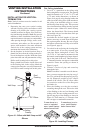
PRESSURE TESTING GAS SUPPLY
PIPING SYSTEM
Test Pressures In Excess Of 1/2 PSIG
(3.5 kPa)
1. Disconnect replace and its individual equip-
ment shutoff valve from gas supply piping
system. Pressures in excess of 1/2 psig (3.5 kPa)
will damage replace gas regulator.
2. Cap off open end of gas pipe where equipment
shutoff valve was connected.
3. Pressurize supply piping system by either
opening propane/LP supply tank valve for
propane/LP gas replace or opening main gas
valve located on or near gas meter for natural
gas replace or using compressed air.
4. Check all joints of gas supply piping system.
Apply noncorrosive leak detection uid to all
joints. Bubbles forming show a leak. Correct
all leaks at once.
5. Reconnect replace and equipment shutoff
valve to gas supply. Check reconnected ttings
for leaks.