


Special offers from our partners!

Find Replacement BBQ Parts for 20,308 Models. Repair your BBQ today.
www.desatech.com
116647-01B12
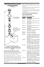
VENTING INSTALLATION INSTRUCTIONS
Continued
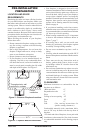
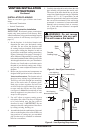
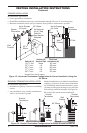
Vertical (V) Required
Vertical (V) Vertical Pipe Horizontal (H)
*43
3
/
4
" min. None 30" max.
53
3
/
4
" min. 1 ft. 48" max.
65
3
/
4
" min. 2 ft. 60" max.
77
3
/
4
" min. 3 ft. 84" max.
89
3
/
4
" min. 4 ft. 20' max.
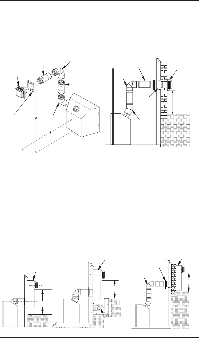
* Ground Floor Corner Venting
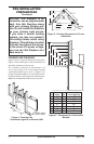
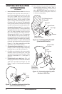
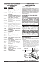
Figure 15 - Horizontal Termination Conguration for Corner Installation Using One
90° Elbow
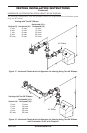
Square
Termination
Wall
Firestop
Not to Exceed
(H) Limits
As Required
for (V), See
Chart for
Pipe Section
Required
45°
Elbow
90° Elbow
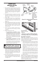
90°
Elbow
Square
Termination
Wall
Firestop
45°
Elbow
Not to Exceed
(H) Limits
12" Min.
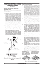
CORNER INSTALLATION
Recommended Applications:
• Corner ground oor installation
• Ground oor installation where pipe vents horizontally through wall (over 12" horizontal pipe)
• Basement installation where one foot clearance from ground to termination is possible
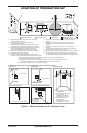
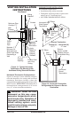
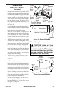
SNORKEL TERMINATION INSTALLATION
Recommended Applications:
• Installations requiring a vertical rise on building
exterior
• Any installation using snorkel termination to
achieve one foot above ground
Snorkel
Termination
12" Min.
12" Min.
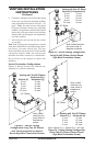
Adequate
Drainage
Snorkel
Termination
Snorkel
Termination
90° Elbow
12" Min.
Wall
Firestop
Snorkel terminations are available for installations
requiring a vertical rise on the exterior of the build-
ing. If installing snorkel termination below grade,
you must provide proper drainage to prevent water
from entering snorkel termination (see Figure 16).
Do not back ll around snorkel termination.
Figure 16 - Snorkel Termination Congurations for Below Ground Installation