


Special offers from our partners!

Find Replacement BBQ Parts for 20,308 Models. Repair your BBQ today.
www.desatech.com
116647-01B 5
PRE-INSTALLATION
PREPARATION
LOCATION AND SPACE
REqUIREMENTS
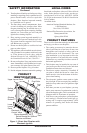
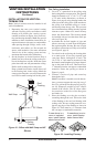
Determine the safest and most efcient location
for your DESA direct-vent replace. Make sure
that rafters and wall studs are not in the way of the
venting system. Choose a location where the heat
output is not affected by drafts, air conditioning
ducts, windows or doors. Figure 2 shows some
common locations. Be aware of all restrictions and
precautions before deciding the exact location for
your replace and termination cap.
When deciding the location of your replace,
follow these rules:
• Do not connect this replace venting to a chim-
ney ue serving a separate solid-fuel burning
replace or appliance.
• Due to high temperatures, do not locate this
replace in high trafc areas, windy or drafty
areas or near furniture or draperies.
• Proper clearances must be maintained.
• If your replace is to be installed directly on
carpeting, vinyl tile or any combustible mate-
rial other than wood, it must be installed on a
metal or wood panel extending the full width
and depth of the replace. See Figure 3.
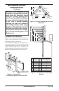
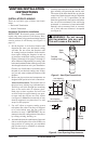
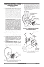
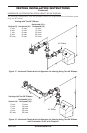
Figure 2 - Common Fireplace Locations
Flush with a wall
Through exterior wall
enclosed in a chase
Corner
installation
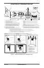
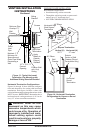
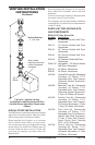
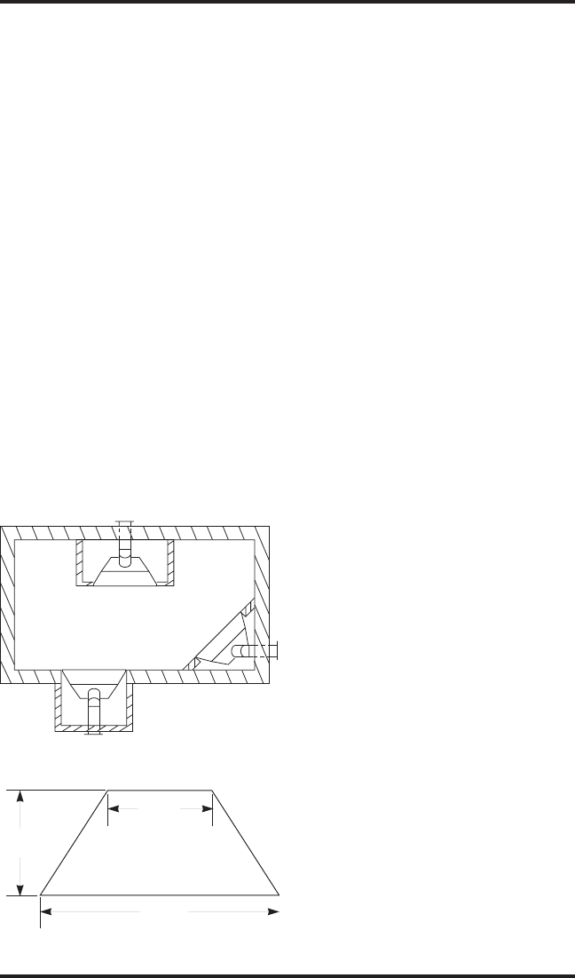
Figure 3 - Fireplace Bottom Dimensions
D
RW
FW
22
1
/
2
"
16
5
/8"
34
3
/
8
"
• Your replace is designed to be used in zero
clearance installations. Wall or framing material
can be placed directly against any exterior sur-
face on the back, sides or top of your replace,
except where standoff spacers are integrally
attached. If standoff spacers are attached to your
replace, these spacers can be placed directly
against wall or framing material. See framing
details on page 6.
• If you plan on installing a television or enter-
tainment center recessed above your replace, it
is recommended that you maintain a minimum
18" above top of louver opening.
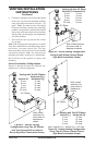
• When locating termination cap, it is important
to observe the minimum clearances shown in
Figure 7, page 7.
• If recessing into a wall, you can avoid extra
framing by positioning your replace against
an already existing framing member.
• Do not recess termination cap into a wall or
siding.
• You may paint the termination cap with 450º F
heat-resistant paint to coordinate with the exterior
nish.
• There must not be any obstruction such as
bushes, garden sheds, fences, decks or util-
ity buildings within 24" from the front of the
termination cap.
• Do not locate termination cap where excessive
snow or ice build up may occur. Be sure to clear
vent termination area after snow falls to prevent
accidental blockage of venting system. When
using snow blowers, do not direct snow towards
vent termination area.
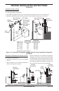
CLEARANCES
Minimum clearances to combustibles for the
replace are as follows:
*Back and sides 0"
Perpendicular walls 6"
Floor 0"
Ceiling to louver opening 42"
Front 36"
Top 0"
Vent (See venting instructions for
specic venting clearances.)
Combustible material with a maximum thick-
ness of 5/8" may be ush with the top front of
replace.
* For back and sides of replace, do not pack with
insulation or other materials. Zero inch clearance
to combustible materials are for framing purpose
only.