


Special offers from our partners!

Find Replacement BBQ Parts for 20,308 Models. Repair your BBQ today.
www.desatech.com
116647-01B 11
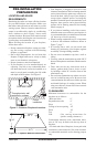
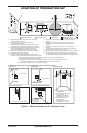
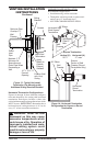
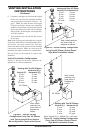
Figure 13 - Typical Horizontal
Termination Cap Mounting with
Additional Siding Standoff Installed
Siding
Standoff
Screws
High Wind
Termination
Apply
Mastic to
Outside
Edge of
Standoff
Exterior Wall
with Vinyl
Siding
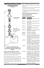
10
3
/4" x 10
3
/4"
Framed
Opening
Maintain 1"
Minimum Air
Space Around
Outer Pipe When
Penetrating a
Wall
Minimum Pipe
Overlap 1
1
/4"
Wall
Firestop
Direct
Vent
Pipe
VENTING INSTALLATION
INSTRUCTIONS
Continued
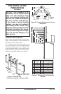
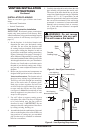
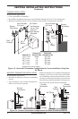
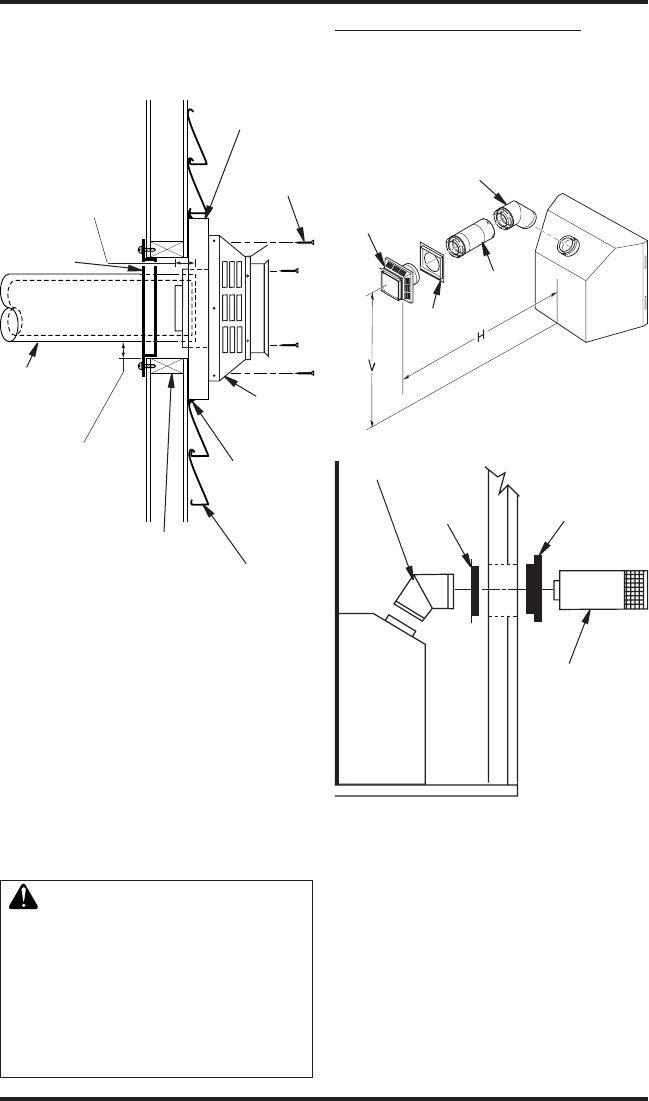
Horizontal Termination Congurations
Figures 14 through 18 show different congura-
tions and alternatives for venting with horizontal
termination. Each gure includes a chart with
critical minimum and maximum dimensions which
MUST be met. IMPORTANT: Remember that a
horizontal run of venting must have a 1/4" rise for
every 12" of run toward the termination.
WARNING: Never run vent
downward as this may cause
excessive temperatures which
could cause a re. Operation of
improperly installed and main-
tained venting system could
result in serious injury, property
damage or loss of life.
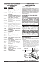
Vertical (V) Horizontal (H)
29
3
/
4
" 17" max.
Horizontal High
Wind Square
Termination
Wall
Firestop
45° Elbow
Figure 14 - Horizontal Termination
Conguration for Square or Round
Termination
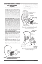
45° Elbow
Wall
Firestop
Horizontal
Round
Termination
Exterior
Portion of Wall
Firestop (Round
Termination Only)
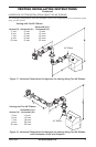
GROUND FLOOR INSTALLATION
Recommended Applications:
• Installation using cabinet surrounds
• Through the wall using round or square termi-
nation (up to 12" horizontal pipe)
• NOT FOR CORNER INSTALLATION
Adjustable
Pipe 12"
Max.
Square Termination