


Special offers from our partners!

Find Replacement BBQ Parts for 20,308 Models. Repair your BBQ today.

G
G
A
A
S
S
L
L
I
I
N
N
E
E
A
A
N
N
D
D
E
E
L
L
E
E
C
C
T
T
R
R
I
I
C
C
A
A
L
L
I
I
N
N
S
S
T
T
A
A
L
L
L
L
A
A
T
T
I
I
O
O
N
N
23
Optional DC Remote Systems
These instructions supersede the section entitled “Hearth Mount” in the Millivolt hand held remote
instructions supplied with the remote.
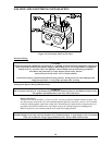
1. Cut cable to length (approximately 12”) for placement in the fireplace.
2. Strip back 1/4” of the insulation from both ends of each wire.
3. Connect two 1/4” female connectors to the wires at one ends of the wire.
4. Insert the opposite ends of the wires into receiver wire terminals and tighten the screws.
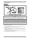
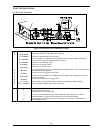
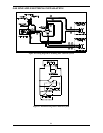
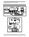
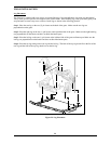
5. Connect the connectors to the two 1/4” male terminals located near the gas valve as shown in Figure
20: Wiring Diagram for Standing Pilot - Millivolt System.
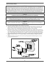
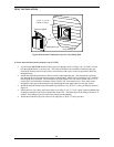
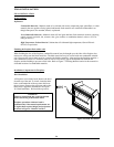
6. Stick velcro pads with self-adhesive backing to bottom of remote receiver and to the floor of the
fireplace behind the door with control switch facing towards the room.
NOTE
Heat reduces battery life. You can protect receiver and extend battery life by mounting the receiver in a wall
or other location outside the fireplace.
Millivolt Control Valve Checklist:
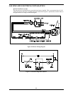
The millivolt (thermopile) control is a self-powered combustion gas control. Refer to Figure 20: Wiring Diagram
for Standing Pilot - Millivolt System. The millivolt system and individual components may be checked with a
millivolt meter having 1-1000 mV range. Conduct each check listed below by connecting the meter test leads to the
terminals indicated. Refer to OPERATING INSTRUCTIONS for safety and lighting instructions.
Thermopile Output Check
Pilot must be lit and the valve control knob turned to the “PILOT” or “ON” position. “RS-ON-OFF” switch
must be in the “OFF” position. Meter leads must be connected to the TP and the TH/TP terminals on the
control valve. If the meter reading is not 325-millivolt minimum, then readjust pilot for maximum millivolt
output. If millivolt reading is still below minimum specified, replace the thermopile.
Thermocouple Output Check
Disconnect thermocouple from valve. Place one lead from meter on the tip of the thermocouple and the
other on the thermocouple copper lead. Turn the valve control knob to “PILOT” and hold the valve knob
in. Start the pilot and read the millivolt output. If the meter reading is not 15-millivolt minimum, then
readjust pilot for maximum millivolt output. If millivolt reading is still below minimum specified, replace
the thermocouple.
Complete Millivolt System Check
Pilot must be lit and the valve control knob turned to the “ON” position. Meter leads must be connected to
the TP and the TH/TP terminals on the control valve.
• Turn RS-ON-OFF switch to the “ON” position.
ü If meter is reading more than 100 millivolt and the main burners do not come on, then replace
control valve.
ü If meter is reading less than 100 millivolt, then refer to TROUBLESHOOTING section of this
manual to determine the cause of the low reading.
• Turn RS-ON-OFF switch to the “RS ” position and wall switch to “ON”
ü If meter is reading more than 100 millivolt and the main burners do not come on, then replace
control valve.
ü If meter is reading less than 100 millivolt, then refer to TROUBLESHOOTING section of this
manual to determine the cause of the low reading.