


Special offers from our partners!

Find Replacement BBQ Parts for 20,308 Models. Repair your BBQ today.
Quick Installation Guide
00825-0100-4664, Rev BB
January 2013
Rosemount 8712 / 8700 Series
9
STEP 4: INSTALLATION
Flanged Sensors
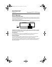
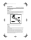
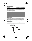
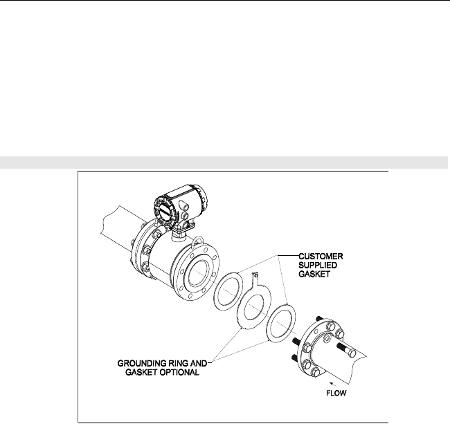
Gaskets
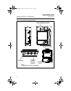
The sensor requires a gasket at each of its connections to adjacent devices or piping. The gasket
material selected must be compatible with the process fluid and operating conditions. Metallic or
spiral-wound gaskets can damage the liner. Gaskets are required on each side of a
grounding ring. All other applications (including sensors with lining protectors or a grounding
electrode) require only one gasket on each end connection.
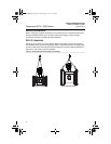
Flange Bolts
NOTE
Do not bolt one side at a time. Tighten each side simultaneously. Example:
1. Snug left
2. Snug right
3. Tighten left
4. Tighten right
Do not snug and tighten the upstream side and then snug and tighten the downstream side.
Failure to alternate between the upstream and downstream flanges when tightening bolts
may result in liner damage.
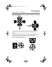
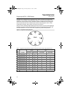
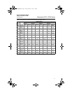
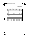
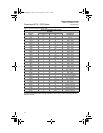
Suggested torque values by sensor line size and liner type are listed in Table 1 for ASME
B16.5 (ANSI) and Table 2 for DIN flanges. Consult the factory if the flange rating of the
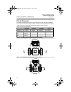
sensor is not listed. Tighten flange bolts on the upstream side of the sensor in the
incremental sequence shown in Figure 7, to 20% of the suggested torque values. Repeat
the process on the downstream side of the sensor. For sensors with more or less flange
bolts, tighten the bolts in a similar crosswise sequence. Repeat this entire tightening
sequence at 40%, 60%, 80%, and 100% of the suggested torque values or until the leak
between the process and sensor flanges stop.
Figure 6. Flanged gasket placement
4664RevBBQIG.fm Page 9 Friday, January 11, 2013 6:13 PM