


Special offers from our partners!

Find Replacement BBQ Parts for 20,308 Models. Repair your BBQ today.
Quick Installation Guide
00825-0100-4664, Rev BB
January 2013
Rosemount 8712 / 8700 Series
19
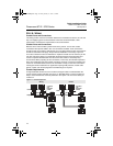
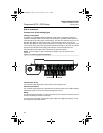
Run the appropriate size cable through the conduit connections in your magnetic flowmeter
system. Run the power cable from the power source to the transmitter. Run the coil drive
and signal cables between the flowmeter sensor and transmitter.
• Installed signal wiring should not be run together and should not be in the same cable
tray as AC or DC power wiring.
• Device must be properly grounded or earthed according to local electric codes.
• Rosemount combination cable part number 08732-0753-1003 (ft) or 08732-0753-2004
(m) is required to be used to meet EMC requirements.
Transmitter to Sensor Wiring
The transmitter can be integral to the sensor or remotely mounted following the wiring
instructions.
Remote Mount Cable Requirements and Preparation
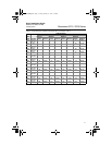
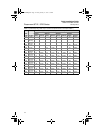
For installations using the individual coil drive and signal cable, lengths should be limited to
less than 1,000 feet (300 meters). Equal length cable is required for each. See Table 7.
For installations using the combination coil drive and signal cable, lengths should be limited
to less than 330 feet (100 meters). See Table 7.
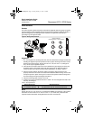
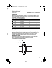
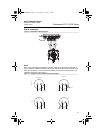
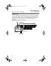
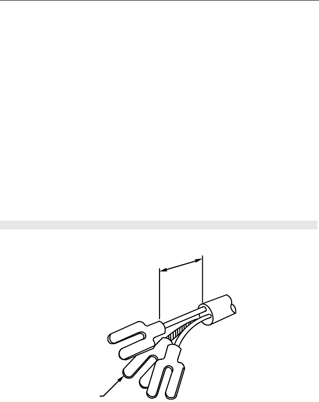
Prepare the ends of the coil drive and signal cables as shown in Figure 15. Limit the
unshielded wire length to 1-inch on both the coil drive and signal cables. Any unsheathed
wire should be wrapped with proper insulation. Excessive lead length or failure to connect
cable shields can create electrical noise resulting in unstable meter readings.
Figure 15. Cable Preparation Detail
Cable Shield
1.00
(26)
NOTE
Dimensions are in inches (millimeters).
4664RevBBQIG.fm Page 19 Friday, January 11, 2013 6:13 PM