


Special offers from our partners!

Find Replacement BBQ Parts for 20,308 Models. Repair your BBQ today.

Quick Installation Guide
00825-0100-4664, Rev BB
January 2013
Rosemount 8712 / 8700 Series
18
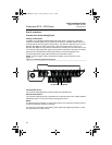
STEP 6: WIRING
Conduit Ports and Connections
This wiring section covers the connection between the transmitter and sensor, the 4-20 mA
loop, and supplying power to the transmitter. Follow the conduit information, cable
requirements, and disconnect requirements in the sections below.
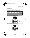
Conduit Ports and Connections
Both the sensor and transmitter junction boxes have ports for
1
/2-inch NPT conduit
connections with optional CM20 or PG 13.5 connections available. These connections
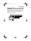
should be made in accordance with national, local, and plant electrical codes. Unused ports
should be sealed with metal plugs. Proper electrical installation is necessary to prevent
errors due to electrical noise and interference. Separate conduits are not necessary for the
coil drive and signal cables, but a dedicated conduit line between each transmitter and
sensor is required. Shielded cable must be used for best results in electrically noisy
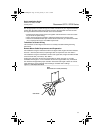
environments. When preparing all wire connections, remove only the insulation required to
fit the wire completely under the terminal connection. Removal of excessive insulation may
result in an unwanted electrical short to the transmitter housing or other wire connections.
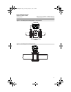
For flanged sensors installed into an application requiring IP68 protection, sealed cable
glands, conduit, and conduit plugs that meet IP68 ratings are required.
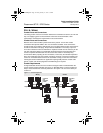
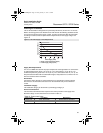
Conduit Requirements
A single dedicated conduit run for the coil drive and signal cable is needed between the
sensor and the remote transmitter. See Figure 14. Bundled cables in a single conduit are
likely to create interference and noise problems in the system. Use one set of cables per
conduit run.
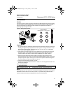
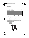
Figure 14. Conduit Preparation
Wrong Correct
Coil Drive
and
Electrode
Cables
Power
Outputs
Power
Outputs
Coil Drive
and
Electrode
Cables
Power
Outputs
Power
Outputs
4664RevBBQIG.fm Page 18 Friday, January 11, 2013 6:13 PM