


Special offers from our partners!

Find Replacement BBQ Parts for 20,308 Models. Repair your BBQ today.
Quick Installation Guide
00825-0100-4664, Rev BB
January 2013
Rosemount 8712 / 8700 Series
22
STEP 6 CONTINUED...
Connect the 4–20 mA Analog Signal
Cabling considerations
If possible, use individually shielded twisted pair cable, either in single pair or multi-pair
varieties. Unshielded cables may be used for short distances, provided ambient noise and
cross-talk will not adversely impact communication. The minimum conductor size is 0.51 mm
diameter (#24 AWG) for cable runs less than 1,500 meters (@ 5,000 ft.) and 0.81 mm
diameter (#20 AWG) for longer distances. Resistance in the loop must be 1000 ohms or less.
The 4–20 mA analog output loop signal may be powered internally or externally. The default
position of the internal/external analog power switch is in the internal position. The
user-selectable power supply switch is located on the electronics board.
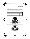
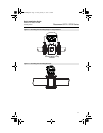
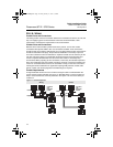
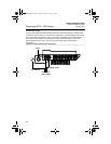
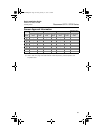
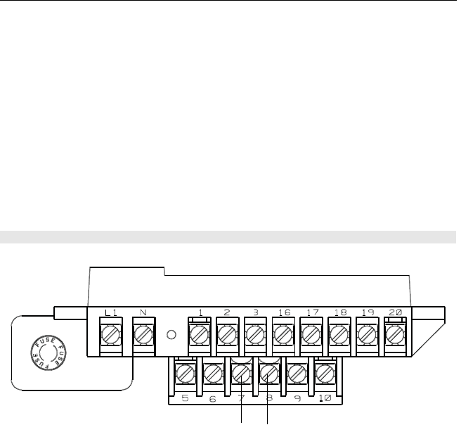
8712E - connect negative (-)DC to Terminal 8 and positive (+)DC to Terminal 7. See
Figure 18.
Internal Power Source
The 4–20 mA analog signal loop is powered from the transmitter itself.
External Power Source
The 4–20 mA analog signal loop is powered from an external power source. HART multidrop
installations require a 10–30 V DC external analog power source.
NOTE:
If a HART Field Communicator or control system will be used, it must be connected across a
minimum of 250 ohms resistance in the loop.
To connect any of the other output options (pulse output and/or digital input/output), consult
the comprehensive product manual.
Figure 18. 8712E Analog Signal Wiring Diagram
–4–20 mA
+4–20 mA
4664RevBBQIG.fm Page 22 Friday, January 11, 2013 6:13 PM