Special offers from our partners!

Find Replacement BBQ Parts for 20,308 Models. Repair your BBQ today.

Quick Installation Guide
00825-0100-4664, Rev BB
January 2013
Rosemount 8712 / 8700 Series
25
Step 7: Basic Configuration
Once the magnetic flowmeter is installed and power has been supplied, the transmitter must
be configured through the basic setup. These parameters can be configured through either
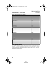
a local operator interface or a HART communication device. A table of all the parameters
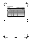
are on page 26. Descriptions of the more advanced functions are included in the
comprehensive product manual.
Basic Setup
Tag
Tag is the quickest and shortest way of identifying and distinguishing between transmitters.
Transmitters can be tagged according to the requirements of your application. The tag may
be up to eight characters long.
Flow Rate Units
The flow rate units variable specifies the format in which the flow rate will be displayed. Units
should be selected to meet your particular metering needs.
Line Size
The line size (sensor size) must be set to match the actual sensor connected to the
transmitter. The size must be specified in inches.
URV (Upper Range Value)
The upper range value (URV) sets the 20 mA point for the analog output. This value is
typically set to full-scale flow. The units that appear will be the same as those selected under
the units parameter. The URV may be set between –39.3 ft/s to 39.3 ft/s
(–12 m/s to 12 m/s). There must be at least 1 ft/s (0.3 m/s) span between the URV and LRV.
LRV (Lower Range Value)
The lower range value (LRV) sets the 4 mA point for the analog output. This value is
typically set to zero flow. The units that appear will be the same as those selected under the
units parameter. The LRV may be set between –39.3 ft/s to 39.3 ft/s (–12 m/s to 12 m/s).
There must be at least 1 ft/s (0.3 m/s) span between the URV and LRV.
Calibration Number
The sensor calibration number is a 16-digit number used to identify sensors calibrated at the
Rosemount factory.
4664RevBBQIG.fm Page 25 Friday, January 11, 2013 6:13 PM


