


Special offers from our partners!

Find Replacement BBQ Parts for 20,308 Models. Repair your BBQ today.
Quick Installation Guide
00825-0100-4664, Rev BB
January 2013
Rosemount 8712 / 8700 Series
21
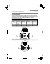
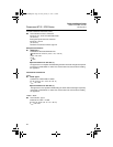
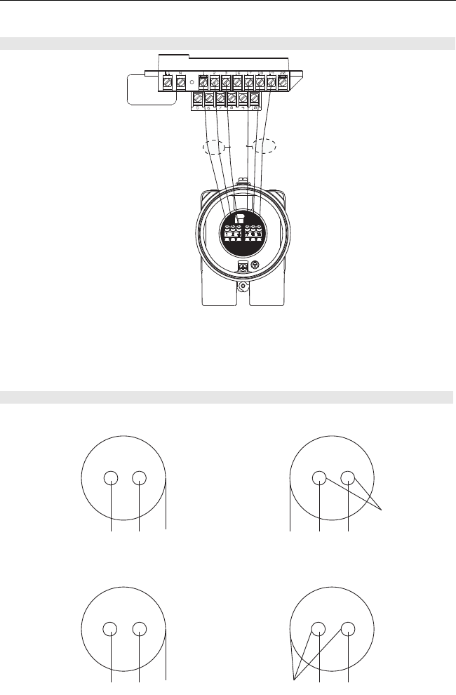
STEP 6 CONTINUED...
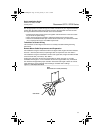
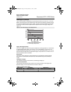
NOTE
When using the Rosemount supplied combination cable, the signal wires for terminals 18
and 19 contain an additional shield wire. These two shield wires should be tied with the main
shield wire at terminal 17 at the sensor terminal block and cut back to the insulation in the
transmitter junction box. See Figure 17.
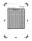
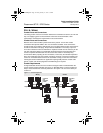
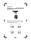
Figure 16. Remote Mount Wiring Diagrams
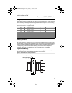
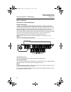
Figure 17. Combination Coil and Signal Cable Wiring Diagram
Transsmiter
Tube
Coil Drive Cable
1 Red 2 Green 3 Shield 17 Shield 18 Black 19 White
Cut Shield
Signal Cable
17 Shield 18 Black 19 White1 Red 2 Green 3 Shield
4664RevBBQIG.fm Page 21 Friday, January 11, 2013 6:13 PM