


Special offers from our partners!

Find Replacement BBQ Parts for 20,308 Models. Repair your BBQ today.
Quick Installation Guide
00825-0100-4664, Rev BB
January 2013
Rosemount 8712 / 8700 Series
20
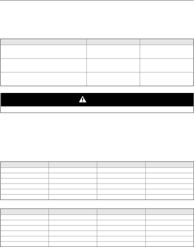
STEP 6 CONTINUED...
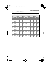
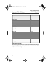
To order cable specify length as quantity desired.
25 feet = Qty (25) 08732-0753-1003
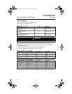
Table 7. Cable Requirements
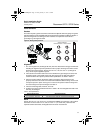
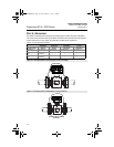
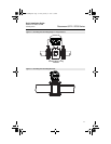
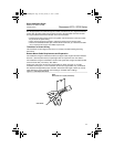
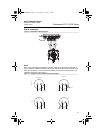
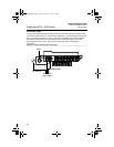
Wiring the Transmitter to the Sensor
When using individual cables for coil drive and signal refer to Table 8. If using the
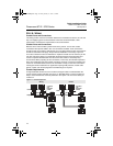
combination coil drive and signal cable, refer to Table 9. See Figure 16 for transmitter
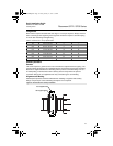
specific wiring diagram.
1. Connect the coil drive cable using terminals 1, 2, and 3 (ground).
2. Connect the signal cable using terminals 17, 18, and 19.
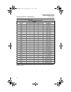
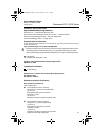
Table 8. Individual Coil and Signal Cables
Table 9. Combination Coil and Signal Cable
Description Length Part Number
Coil Drive Cable (14 AWG)
Belden 8720, Alpha 2442
or equivalent
ft
m
08712-0060-0001
08712-0060-2013
Signal Cable (20 AWG)
Belden 8762, Alpha 2411
or equivalent
ft
m
08712-0061-0001
08712-0061-2003
Combination Cable
Coil Drive Cable (18 AWG) and
Signal Cable (20 AWG)
ft
m
08732-0753-1003
08732-0753-2004
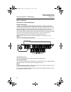
WARNING
Potential Shock Hazard Across Terminals 1 & 2 (40 Vac).
Transmitter Terminal Sensor Terminal Wire Gauge Wire Color
1 1 14 Clear
2 2 14 Black
3 or Ground 3 or Ground 14 Shield
17 17 20 Shield
18 18 20 Black
19 19 20 Clear
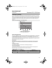
Transmitter Terminal Sensor Terminal Wire Gauge Wire Color
1 1 18 Red
2 2 18 Green
3 or Ground 3 or Ground 18 Shield
17 17 20 Shield
18 18 20 Black
19 19 20 White
4664RevBBQIG.fm Page 20 Friday, January 11, 2013 6:13 PM