


Special offers from our partners!

Find Replacement BBQ Parts for 20,308 Models. Repair your BBQ today.
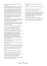
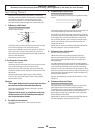
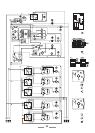
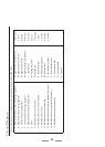
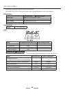
Circuit Diagram
Connection shown in circuit diagram is for single phase. Ratings are for 230V 50Hz
A Right hand end dual circuit hob energy regulator
B Right hand rear hob energy regulator
C Left rear hob energy regulator
D Left hand front hob energy regulator
F Right hand front hob energy regulator
H Clock
J1 Multi function oven thermostat
J2 Multi function oven function switches
J3 Multi function oven fan
J4 Multi function oven fan element
J5 Multi function oven browning element (inner pair)
J6 Multi function oven top element (outer pair)
J7 Multi function oven base element
K1 Right hand oven thermostat
K2 Right hand oven switches
K3 Right hand oven fan
K4 Right hand fan oven element
L Line terminal
M1 Cooling fan switch
M2 Cooling fan
N Neutral terminal
Q1 Grill energy regulator
Q2 Grill elements
R Facia indicator neons
S Hob indicator neons
T1 Oven light switch
T2 Oven light bulb
U Cut-out
Colour Code
b Blue
bl Black
br Brown
gr Green
gy Gray
or Orange
r Red
v Violet
w White
y Yellow