


Special offers from our partners!

Find Replacement BBQ Parts for 20,308 Models. Repair your BBQ today.
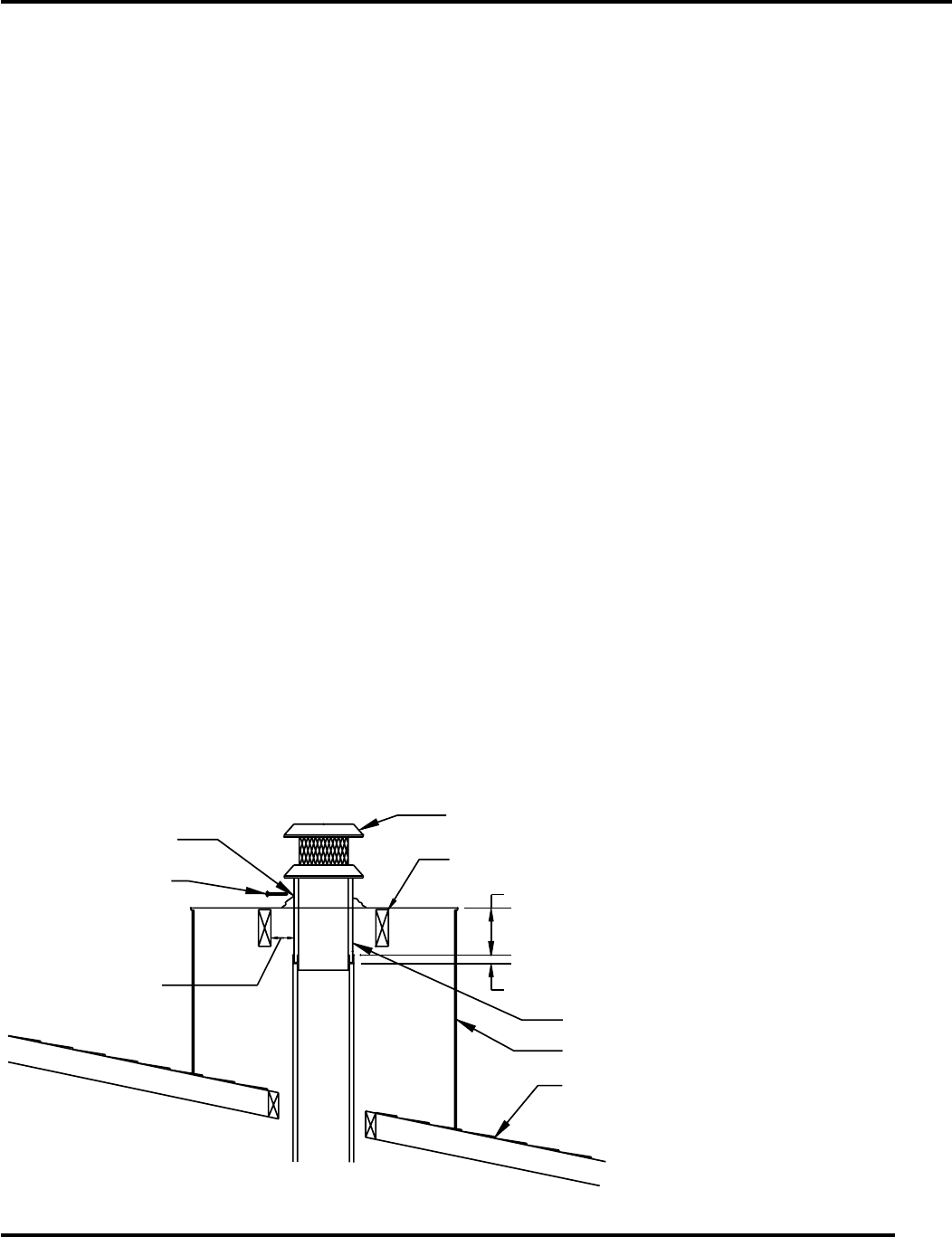
CHIMNEY CAP CHASE INSTALLATION
21
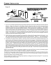
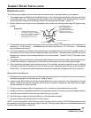
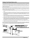
The preinstalled chimney sections should be no more than 10 inches below the top of the chase. The installation
should be planned so that either a two-foot or three-foot chimney section will be used for the top section. This
is necessary to ensure complete engagement of the inlet air telescope and chimney cap into the top section.
C
AUTION: Be careful around electrical wires to avoid the electrical shock hazard of contacting the wires with the
metal chimney components.
N
OTE: When two fireplace chimneys are terminated above the same chase, the centers of the chimney caps
should be at least 24 inches apart to help prevent smoke from a fireplace in use from being drawn down the
chimney of a fireplace that is not in use. Additional spacing between caps or staggering the height of the caps
will further lessen the likelihood of this occurring.
1. Extend the chimney sections until the top of the chimney is not more than 10 inches below the top of the
chase.
2. Center the hole in the chase cover over the chimney. The chase cover overhang should be lanced, formed
over the chase and secured with nails. This prevents water from seeping under the chase cover. If two or
more chase covers are to be used on the same chase, they should be soldered together to form two
watertight seams.
3. Place the inlet air telescope inside the hole in the chase cover and lower it down into the mating pipe of the
chimney until the flange on the telescope section rest on the flange of the chase cover. Note: All telescoping
sections should extend a minimum of three inches inside the mating chimney pipes.
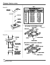
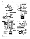
4. Install the SCL or SQL8 chimney cap by placing the cap into the matching duct telescope and flue telescope
of the last chimney section as shown by Figure 23. Lower the cap until the brackets on the bottom of the
chimney cap rests on the raised flange of the flat flashing, punch or drill 1/8 inch diameter holes in the
raised flange of the flat flashing, and fasten the cap to the flashing with the No. 8 screws provided.
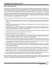
5. Check all parts of the chimney and chimney cap to assure that no parts have been damaged or bent during
installation and that all parts have been installed properly.
N
OTE: The metal used for the chimney and chimney cap has a rust-protective coating but the cut edges of the
parts are not protected. To prevent rusting and rust staining of nearby structures, exposed parts of the chimney
and chimney cap should be detergent-washed and painted with galvanized primer paint.
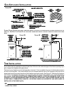
MAINTAIN CHIMNEY
SYSTEM AIR SPACE
CLEARANCES TO
COMBUSTIBLES
ABOVE ROOF LINE.
SCREW
CHIMNEY CAP SUPPORT
BRACKETS. 3 PLACES.
SCL OR SQLB CHIMNEY CAP DESIGN INCORPORATES LONGER DUCT
AND FLUE PIPE FOR CHASE TYPE INSTALLATION.
FLAT FLASHING OR CHASE COVER WITH 11-1/4" MIN. DIA. HOLE
10" MAX. SPACE BETWEEN CHIMNEY SECTION AND CHASE COVER.
3" MIN OVERLAP
INLET AIR TELESCOPE
CHASE
ROOF
FIGURE 23
53D9031. Rev 1 03/03