


Special offers from our partners!

Find Replacement BBQ Parts for 20,308 Models. Repair your BBQ today.
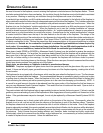
The ability of insulating material to retard the transfer of heat may be expressed as either Thermal Conduc-
tance (C), Thermal Conductivity (K), or Thermal Resistance (R). The mathematical relationship of these
values and the formulas for converting one value to another is as follows:
C=K divided by the material thickness
(Example C = .43 divided by 1/2 (.50)
C = .86)
K = C multiplies by the material thickness
(Example K = .86 multiplied by 1/2 (.50)
K = .43)
R= The material thickness divided by K
(Example R = 1/2 (.50) divided by .43
R = 1.16)
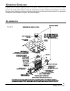
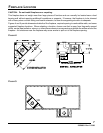
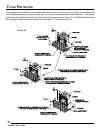
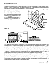
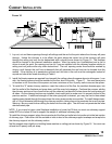
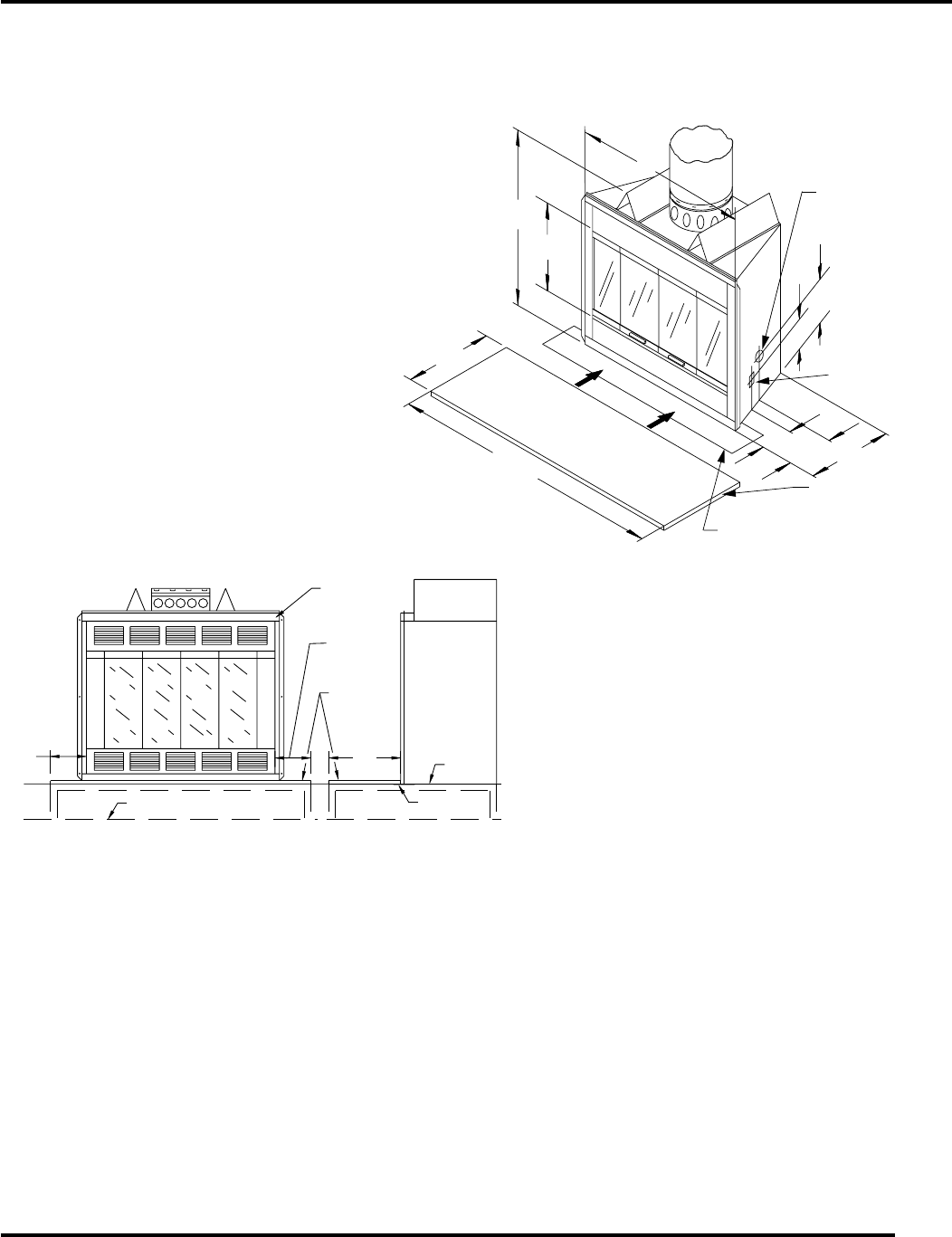
FLOOR PROTECTION
With either type hearth extension minor shifting of the supporting floor or expansion and contraction may
eventually cause a crack to develop between the hearth extension and the face of the fireplace. To help
prevent the crack from developing, the hearth extension materials must be firmly fastened in place. Wall ties
should be screwed to the face of the fireplace and imbedded in the mortar joints of brick, stone, or other non-
combustible materials. The metal safety strip packed with the fireplace must be placed beneath the fireplace
and extended under the hearth extension or into a mortar joint of the hearth extension as shown by Figures 10,
11, and 12. In the event a crack does eventually develop, the metal safety strip will serve as a barrier to
prevent sparks or embers from falling from the fireplace onto combustible flooring materials.
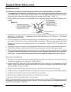
The hearth extension must not block the side air vents, or air inlet louvers on the lower front of the fireplace.
These openings must be unobstructed to assure an adequate flow of cooling air around the firebox. If the
fireplace is equipped with a blower, or may be equipped with one at a later date, the hearth extension must not
prevent the removal of the lower louver panel for servicing the blower. Plan adequately by determining the
finished height of the hearth extension to be used and elevate the fireplace on a platform, if necessary, to
prevent obstructing the air openings or lower louvered panel.
11
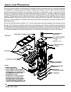
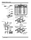
SAFETY STRIPSAFETY STRIP
21"21"
8 3/4"8 3/4"
FLOOR LEVELFLOOR LEVEL
7 1/8"7 1/8"
5"5"
3" X 36" (MIN)3" X 36" (MIN)
9 1/2"9 1/2"
38"38"
37 1/2"37 1/2"
19 1/2"19 1/2"
52" (MIN.)52" (MIN.)
16" (MIN.)16" (MIN.)
GASGAS
OPENINGOPENING
JUNCTIONJUNCTION
BOX OPENINGBOX OPENING
HEARTHHEARTH
EXTENSIONEXTENSION
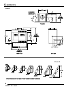
FIGURE 11
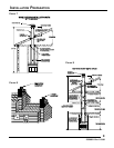
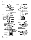
FIREPLACE
FIREPLACE
HEARTH
HEARTH
FLOOR
FLOOR
METAL
METAL
WARNING:
THE HEARTH EXTENSION AND
THE HEARTH EXTENSION AND
THE GALVANIZED METAL STRIP
THE GALVANIZED METAL STRIP
SHOULD BE INSTALLED ONLY IN
SHOULD BE INSTALLED ONLY IN
A HORIZONTAL RELATIONSHIP TO
A HORIZONTAL RELATIONSHIP TO
THE FIREPLACE, AS ILLUSTRATED.
THE FIREPLACE, AS ILLUSTRATED.
8"
8"
MIN.
MIN.
FLOOR LINE WITH
FLOOR LINE WITH
8"
MIN.
SAFETY STRIP
SAFETY STRIP
RAISED HEARTH
RAISED HEARTH
16"
16"
MIN.
MIN.
FIGURE 12
53D9031. Rev 1 03/03