


Special offers from our partners!

Find Replacement BBQ Parts for 20,308 Models. Repair your BBQ today.
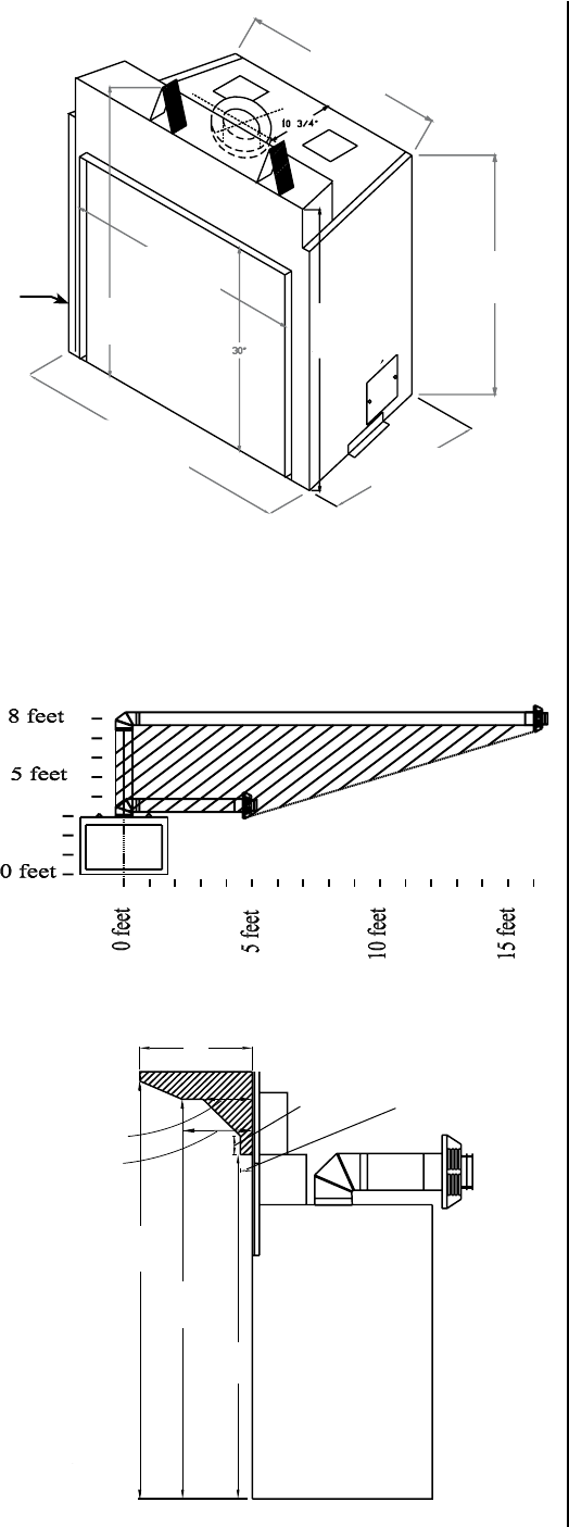
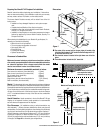
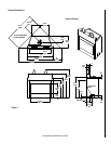
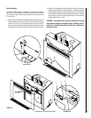
Figure 1
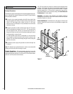
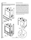
Figure 2
7
NOTE: DIAGRAMS & ILLUSTRATIONS ARE NOT TO SCALE.
Preparing Your Ravelle™ 42 Fireplace For Installation
Read all instructions before beginning your installation. If instructions
have not been read carefully, your installation could void your warranty
and may create a serious fire, health, or other safety hazard.
The Lennox Hearth Products warranty will be voided if one of the fol-
lowing occurs:
• Installation of any damaged fireplace or vent system compo
-
nent.
• Unauthorized modification of the direct vent system.
• Installation other than as instructed by Lennox Hearth Products,
Security™, or Simpson Dura-Vent.
• Installation of any fireplace or vent system component not manu-
factured or approved by Lennox Hearth Products, Security™ or
Simpson Dura-Vent.
When planning the installation for your Ravelle 42 gas fireplace, it’s
necessary to consider the following:
• Where the unit is to be installed
• The vent system configuration to be used
• Gas supply (NG or LP)
• Electrical wiring
• Framing and finishing
• Optional accessories
Clearances to Combustibles
Minimum clearances include any projections such as shelves, window
sills, mantels, spacers/standoffs or surfaces to combustible construction
etc. above the appliance. Paint or lacquer used to finish the mantel
must be heat resistant in order to avoid discoloration.
Minimum clearances to combustible materials in inches:
Front corners to enclosure (from stand-offs) 0 (0mm)
Rear corners to enclosure (from stand-offs) 0 (0mm)
Top to header (from stand-offs) 0 (0mm)
Bottom of unit to floor 0 (0mm)
Edge of door glass to side wall and side trim 7-1/2 (191mm)
Back to enclosure (from stand-offs) 0 (0mm)
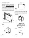
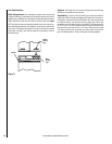
Mantel: The drawing at the lower right shows the minimum distances
from the base of the fireplace to combustible mantel and facing material.
Combustible materials may be placed above and within the shaded areas.
If your fireplace has an arched face, the combustible mantel facing mate-
rial may curve with the arch of the face as long as a minimum distance
of 10” is maintained between the top of the face and the combustible
facing material.
Hearth Protection: Hearth protection in front of the Ravelle™ 42 gas
fireplace is not required. However, hearth protection is recommended
and will enhance the appearance of the fireplace.
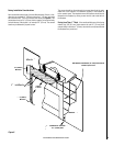
Pipe Clearances: All installations using a vertical termination cap
must maintain 1” (25mm) clearance between the direct vent pipe and
combustibles. For horizontal terminations, when the top of the horizontal
run of pipe is less than 8 feet (2.4 M) above the base of the fireplace, 1”
(25mm) clearance on the sides and bottom and 5” (127 mm) on the top
of the pipe is required. For those horizontal runs at or above 8 feet, 1”
(25 mm) is required on the sides and bottom and 2” (51 mm) on the top
of the pipe. See Page 19 for allowable pipe configurations.
uThe center of the access hole for the gas piping is located at the
left side of the fireplace 6-7/8” back from the front edge and 2-1/8”
up from the base of the unit.
vThe electrical access is located at the right lower rear of the fire-
place.
w These dimensions include the 3/4” stand-offs.
*
*
Installations in the shaded
area require five inches
clearance on top of pipe.
Fireplace side view
(drawing not to scale)
Base of Fireplace
Dimensions
Mantel and Facing Material (side view)
29-3/4”
(756mm)
w
35-1/2”
(902mm)
20-3/4”
(527mm)
w
38-1/4”
(972mm)
47-3/4”
(1213mm)
41”
(1041mm)
43”
(1092mm)
12”
(305mm)
5-1/4”
(133mm)
49-5/8”
(1261mm)
47-5/8”
(1210mm)
41-5/8”
(1057mm)
7-1/2”
(191mm)
2”
(51mm)
1-1/4”
(32mm)
u
v