


Special offers from our partners!

Find Replacement BBQ Parts for 20,308 Models. Repair your BBQ today.

23
NOTE: DIAGRAMS & ILLUSTRATIONS ARE NOT TO SCALE.
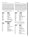
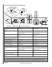
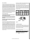
Fuel
Type
Inlet Pressure Manifold Pressure
Desired Minimum Maximum On Hi
Fire
On Lo
Fire
Natural
Gas
7" WC 5" WC 10.5" WC 3.5" WC 1.7" WC
LP Gas 11" WC 11" WC 13" WC 11" WC 5.4” WC
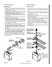
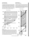
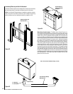
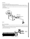
Gas Line Installation
The Ravelle™ 42 gas fireplace must be connected to the gas line in ac-
cordance with local codes and/or the National Fuel Gas Code, ANSI Z223.1
(In Canada, the current CAN/CSA B149.1 installation code). The gas line
should enter the fireplace on the left side (see diagrams on Pages 8 and
9). If the gas line enters the unit from the right side, the line will need to
be disconnected to remove the fan. The fireplace comes with a flex line
attached to the supply side of the gas valve. The fitting on the end of the
flex line can receive a 1/2” female iron pipe coupling, a 3/8” male iron
pipe, or a shut-off valve. There is sufficient room to locate the shut-off
valve under the firebox at the end of this flex line, however, local codes
may require the shut-off to be located on the exterior of the fireplace. After
connecting the gas line, all joints in the line and connections at the valve
should be checked for leaks before final positioning of the unit. Conduct a
gas leakage test of the appliance piping and control system downstream
of the shutoff valve in the supply line to the appliance.
Gas Pressure Requirements
A MAJOR CAUSE OF OPERATING PROBLEMS WITH GAS APPLI
-
ANCES IS IMPROPER GAS PRESSURE!
The most important item to check during the initial installation
and the first thing to check when operating problems occur is
gas pressure!
This fireplace will not function properly unless the required
gas pressure is supplied. See the table on this page for gas
pressure requirements.
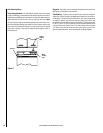
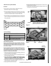
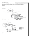
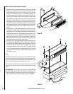
Two pressure taps are provided on the fireplace’s valve to check gas
pressures. To access the taps remove the two socket head screws to
remove the valve control panel/heat shield. The taps are located below
the on/off/pilot knob (see Figure 32
). The left tap is the inlet (supply)
pressure side. To check inlet pressure (with the fireplace burning) insert
a small flat bladed screwdriver into the tap and turn a half turn counter-
clockwise. Cover the tap with the line from a manometer and read the
pressure. Close the tap gently but securely after completing the check.
The manifold (outlet) tap is to the right of the inlet tap. To check manifold
pressure (with the fireplace burning at the high burn setting) insert a
small flat bladed screwdriver into the tap and turn a half turn counter-
clockwise. Cover the tap with the line from the manometer and check
the pressure. Again close the tap gently but securely after completing
the check. Check the taps for gas leaks with a gas leak test solution
(retighten if necessary).
LP and Natural Gas Supplies
Your Ravelle gas fireplace is equipped from the factory for use with
natural gas only as specified on the Safety / Listing label attached to the
appliance. This appliance can only be operated using propane gas (LP)
if a certified fuel conversion kit provided by Lennox Hearth Products is
installed by a qualified service technician.
Also check the orifice size on the label on the igniter bracket. It must be
the correct size for the fuel and altitude.
Do not run propane tank dry. Running the tank dry may cause a
hazardous condition due to pressure drop in empty tank.
Solid fuel is NOT to be used with this unit.
If the pressure is not sufficient, make sure the gas supply line is large
enough, the supply regulator is properly adjusted and the total gas load
for the residence does not exceed the amount supplied.
Note: The appliance and its individual shut-off valve must be disconnected
from the gas supply piping system during any pressure testing of that
system at test pressures in excess of 1/2 psig. The appliance must be
isolated from the gas supply piping system by closing its individual
manual shut-off valve during any pressure testing of the gas supply piping
system at test pressures equal to or less than 1/2 psig. Check with your
gas supplier or plumber.
Inlet (Supply)
Pressure Tap
Figure 32
The Manifold
(Outlet) Tap
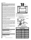
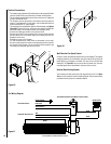
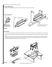
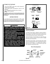
TP/TH
TH
TP
SIT Millivolt Gas Valve