


Special offers from our partners!

Find Replacement BBQ Parts for 20,308 Models. Repair your BBQ today.

27
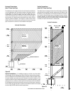
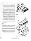
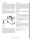
NOTE: DIAGRAMS & ILLUSTRATIONS ARE NOT TO SCALE.
Expanded View
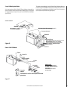
Bend Tabs Under
Cover Plate
Flapper Plate
Starter Ring
Starter Ring Adapter
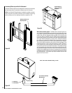
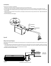
Duct Assembly:
The duct has zero clearance to combustibles.
1. Remove the cover plate from the top of the fireplace. Save the screws and discard the plate.
2. Insert the starter ring into the starter ring adapter and bend the tabs under to secure the ring to the adapter. See the expanded view below.
3. Place the adapter with the attached starter ring over the flapper plate and secure them to the top of the fireplace using the four screws that held
the cover plate.
4. Fasten the remaining components of the duct: flex line, duct adapter, wall stack and fan box using at least three sheet metal screws and aluminum
duct tape at each joint.
5. Secure the ducting to prevent sagging.
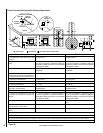
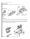
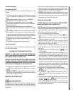
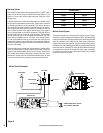
Wiring of the Forced Air System:
Disconnect the electrical supply to the fireplace at the electrical panel prior to wiring the forced air system fan. All wiring should be done by a quali-
fied electrician.
1. After installing the fan box and ducting from the fireplace to the fan box, the wiring of the fan box should be undertaken. Included in the ducting kit
are two electrical switch boxes. One is for installation in new construction and the other is to be used in a remodel. Select the switch box needed
and fasten it to the wall framing in the room in which the fan box is located.
(Instructions continue on the following page).
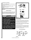
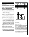
Green (Ground)
Black (Hot)
White (Neutral)
Speed Control
Blower
From
Power
Source
Figure 40
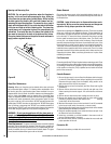
Figure 41
Supply Leads
from Fireplace
Speed Control
Black (Hot)
White (Neutral)
Green (Ground)
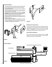
Cover Plate
Flapper Plate
Starter Ring Adapter
Starter Ring
Bend Tabs Under
Expanded View