


Special offers from our partners!

Find Replacement BBQ Parts for 20,308 Models. Repair your BBQ today.
18
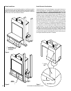
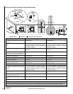
Flue Restrictors
The flue restrictor settings shown in Figures 22 and 23 are for typical
installations and may need to be adjusted from standard to take into
account other variables in the installation to achieve proper combustion.
See Flue Restrictor Guidelines on this page to assist you in making a
proper flue restrictor adjustment.
The Ravelle™ 42 gas fireplace uses balanced flue technology to ensure
proper combustion. Flue restrictors may need to be installed depending
on the vent configuration of your fireplace. The drawings on Page 19
show all the allowable pipe configurations for the Ravelle 42 gas fireplace.
To properly install the flue restrictor, find your pipe configuration in the
drawings on Page 19 and note which restrictor setting is recommended.
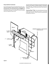
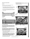
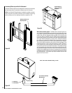
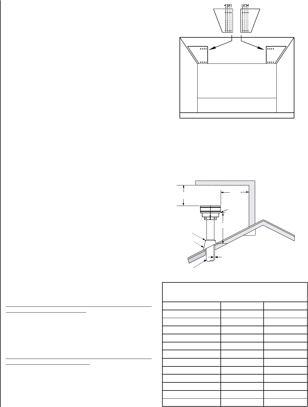
The flue restrictors and four black self-tapping 5/32” allen head screws
can be found in the firebox in a plastic bag. The restrictors should be
placed over the openings at both sides of the ceiling of the firebox. For
each restrictor, two self-tapping 5/32” allen head screws should be in
-
stalled in either holes 1, 2, 3, or 4 in the restrictor and screwed into the
two holes in the firebox ceiling. (There are four holes at each side of the
firebox ceiling to receive only two screws. Insert the screws into either
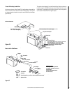
two holes). See the drawing to the right for the location of hole numbers
on the restrictor. The numbered holes in which the screws are inserted
in the restrictor should correspond to the restrictor position numbers
found on the drawings for your pipe configuration. Restrictor positions
are based on tests run in a laboratory. The optimum restrictor positions
may need to be adjusted slightly depending on the conditions surround
-
ing the residential installation. Do not adjust restrictors to a point where
the fireplace is sooting.
Notes: The higher the number of the flue restrictor position, the greater
amount of combustion air will be delivered.
Flue Restrictor Adjustment Guidelines
After the flue restrictors have been set to the standard settings as shown
in Figures 22 and 23, the burner flame appearance should be evaluated
to determined if the flue restrictors need to be set to a different position
to adjust for variables in your installation. Light the appliance and allow
it to burn for 20 minutes. See
Flame Color and Behavior on Page 30 to
determine if you have a proper burner flame appearance. If the proper
flame appearance cannot be achieved, the flue restrictor may need to be
set to a different position. See the following guidelines to determine if
you need to readjust the flue restrictors.
Before proceeding, confirm the manifold and inlet gas pressure is correct,
primary air shutter is properly adjusted, venting system connections are
secure and not blocked and if you are at a high elevation, ensure unit has
been properly derated:
Symptoms - Lack of Combustion Air
If the symptoms listed below are present, you may need to adjust the
flue restrictor to a more open position.
• Flame appears yellow
• Floating Flames (lazy, ill defined, quiet, may roll)
• Sooting
• Pilot becomes yellow and appliance shuts down
Symptoms - Excessive Combustion Air
If the symptoms listed below are present, you may need to adjust the
flue restrictor to a more closed position.
• Low Flame
• Pilot pulls and appliance shuts down
• Pilot flame ghosts
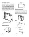
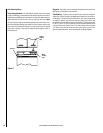
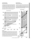
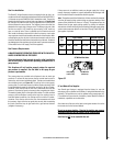
Termination Heights For Vents
Above Flat Or Sloped Roofs
Ref. NFPA 54 / ANSI Z223.1
Roof Pitch * Feet * Meters
Flat to 6/12
1.0 0.3
6/12 to 7/12
1.25 0.38
7/12 to 8/12
1.5 0.46
8/12 to 9/12
2.0 0.61
9/12 to 10/12
2.5 0.76
10/12 to 11/12
3.25 0.99
11/12 to 12/12
4.0 1.22
12/12 to 14/12
5.0 1.52
14/12 to 16/12
6.0 1.83
16/12 to 18/12
7.0 2.13
18/12 to 20/12
7.5 2.29
20/12 to 21/12
8.0 2.44
12
X
Roof Pitch is X/12
2 FT
MIN.
2 FT MIN.
Lowest
Discharge
Opening
H*
*H = MINIMUM HEIGHT FROM ROOF TO
LOWEST DISCHARGE OPENING OF VENT
TERMINATION HEIGHTS FOR VENTS ABOVE
FLAT OR SLOPED ROOFS
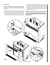
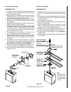
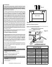
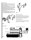
Horizontal Overhang
Vertical
Wall
Vent
Termination
Storm Collar
Concentric
Vent Pipe
Flashing
1 inch (25.4 mm) Minimum
Clearance to Combustibles
Vertical Vent Termination Clearances
The vent / air intake termination clearances above the high side of an
angled roof is as shown in the table below.
Figure 20
NOTE: DIAGRAMS & ILLUSTRATIONS ARE NOT TO SCALE.
Figure 21
Restrictors
Interior of Firebox
Restrictors
Interior of Firebox