


Special offers from our partners!

Find Replacement BBQ Parts for 20,308 Models. Repair your BBQ today.

32
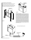
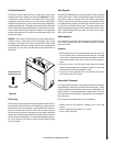
Operating Options
Your Ravelle™ 42 gas fireplace comes equipped with an “On/Off” rocker
switch used to turn the burner on and off while the pilot light is on. The
switch is a round rocker switch located behind the lower door of the
fireplace’s face.
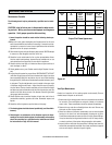
A wall-mounted switch, a millivolt wall thermostat, or a remote control
can be used to supplement the rocker switch. The gas valve is powered
by millivolts generated by the pilot assembly. This millivolt system is
very sensitive to electrical resistance, therefore make sure all connec
-
tions are tight, clean and free from corrosion. Do not splice any millivolt
wires. Consult the table on this page to determine the proper gage of
wire for the thermostat or wall switch connections. This table refers to
the total length of the wire (out to the switch and back). The thermostat
must be a millivolt type. A 24-volt furnace thermostat will not work.
Never hook up household current - 120 Volts - to the millivolt system.
It is not recommended to hook up any more than two switches to the
fireplace (for example a rocker switch and a wall thermostat). Additional
switches may affect the system resistance and increase the chance of
the burner not igniting.
Follow the instructions included with the thermostat or remote control
for wiring. The thermostat, remote control and rocker switch will turn the
burner on and off independently. Be sure to set the rocker switch to the
“Off” position when using the thermostat or remote control and set the
thermostat or remote control to the lowest temperature when you wish
to use the rocker switch only, otherwise one may override the other.
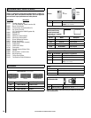
Thermostat Wire
Wire Size Maximum Length
12 Gage 100 Feet
14 Gage 64 Feet
16 Gage 40 Feet
18 Gage 25 Feet
20 Gage 16 Feet
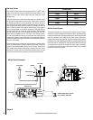
Millivolt Control System
This fireplace operates on a millivolt control system. As such, no addi-
tional power supply is needed for the fireplace to heat. The pilot assembly
contains a thermocouple, that when heated by the pilot flame, generates
electricity (millivolts- mV=1/1000 of a volt) which opens a valve allow
-
ing gas to flow to the pilot assembly. The pilot assembly also contains a
thermopile, that when heated by the pilot flame, generates electricity that
flows to terminal #1 (labeled THTP) on the gas valve. When the electricity
is conducted from terminal #1 through the on/off switch, thermostat,
or receiver of the remote control to terminal #3 (labeled TH) on the gas
valve, the main burner will ignite.
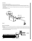
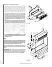
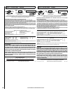
Figure 47
NOTE: DIAGRAMS & ILLUSTRATIONS ARE NOT TO SCALE.
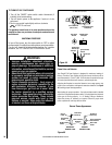
Millivolt Control Schematic
Sparker
Pilot Hood
ON/OFF Rocker Switch, Thermo
-
stat, or Remote Thermostat
Pilot Assembly
Thermocouple
Piezo Igniter
White
Gas Inlet
Pilot Gas Line
Thermopile
Brown
Wiring Terminals
TH
TP
TH/TP