


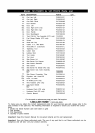
Special offers from our partners!

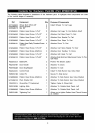
Find Replacement BBQ Parts for 20,308 Models. Repair your BBQ today.
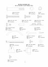
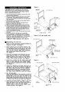
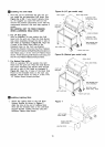
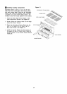
_llnstalling The Grill Head
1. Now that you've assembled the grill cart you
can install the pre-assembled Grill Head. See
Figure 6a or 6b. If you haven't already done
so, we suggest you open the Grill Lid and
remove the packed components. Even with the
components removed, this next step requires 2
people.
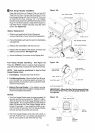
BE CAREFUL NOT TO PINCH FINGERS
WHEN LOWERING HEAD ONTO CART
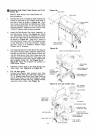
2. For LP Gas grills:
With an assistant, lift and position the Grill
Head onto the grill cart. Place the Side Burner
Gas Valve Assembly through the slot in side of
Grill Head as illustrated in Figure 6a. Align the
4 holes of the Bowl Side Panel to the
threaded holes on the Cart Leg Bracket.
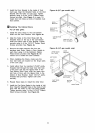
Thread the Electric Wire into the Wire Fastener.
Secure Wire Fastener to Right Rear Bowl location on
Grill Head using 1 of the 1/4"xl/2" Pattern Head
Screw. Finish securing Grill Head to Cart using 3 of
the 1/4"xl/2" Pattern Head Screws provided.
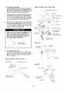
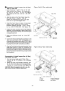
3. For Natural Gas grills:
With an assistant, lift and position the Grill
Head onto the grill cart. Place the Side Burner
Gas Valve Assembly and Electric Wire through
the slot in side of Grill Head as illustrated in
Figure 6b. Align the 4 holes of the Bowl Side
Panel to the threaded holes on the Cart Leg
Bracket. Secure firmly by using 4 of the 1/4"x
1/2" Pattern Head Screws provided.
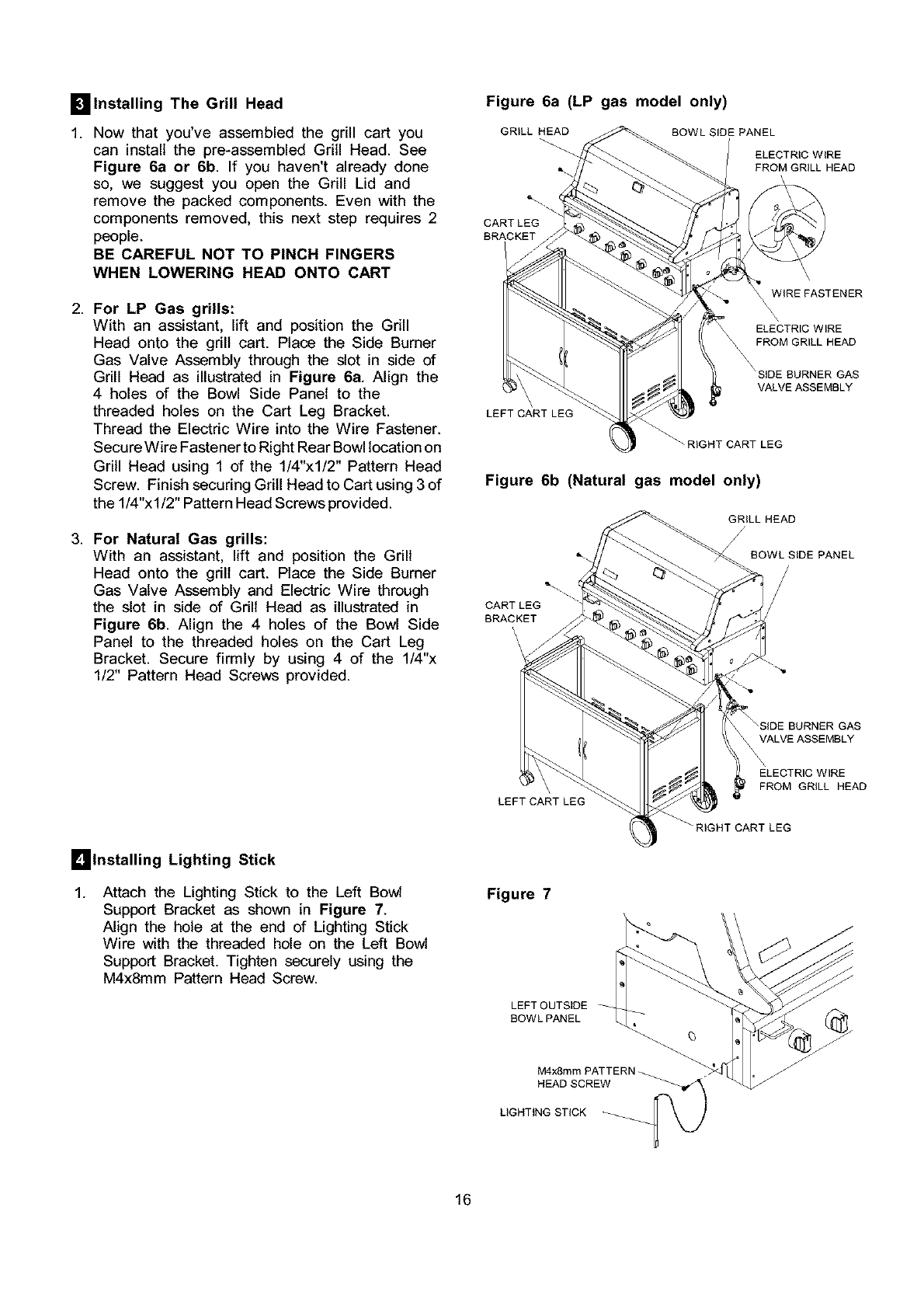
Figure 6a (LP gas model only)
GRILL HEAD BOWL SIDE PANEL
ELECTRIC WIRE
FROM GRILL HEAD
CARTLEG
BRACKET
WiRE FASTENER
FROM C
_\ VALVE ASSEMBLY
LEFT CART LEG
_HT CART LEG
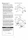
Figure 6b (Natural gas model only)
GRILL HEAD
/
%\ BOWL SIDE PANEL
CARTLEG
BRACKET
\
\
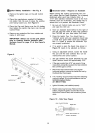
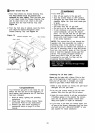
Imlnstalling Lighting Stick
1.
Attach the Lighting Stick to the Left Bowl
Support Bracket as shown in Figure 7.
Align the hole at the end of Lighting Stick
Wire with the threaded hole on the Left Bowl
Support Bracket. Tighten securely using the
M4x8mm Pattern Head Screw.
LEFT CART LEG
BURNER GAS
VALVE ASSEMBLY
ELECTRIC WIRE
FROM GRILL HEAD
_'RIGHT CART LEG
Figure 7
LEFT OUTSIDE
BOWL PANEL
M4x8mmPATTENN_
HEAD SCREW
UGHTtNG STICK
16