


Special offers from our partners!

Find Replacement BBQ Parts for 20,308 Models. Repair your BBQ today.

29
Installing the Insert (continued)
Figure 14
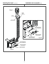
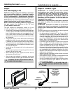
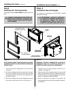
4. Slide the surround against the face of the unit, aligning
the holes in upper and lower, right and left corners and
secure the surround to the unit with the attachment
screws.
NOTE: PLACE THE THREE INSULATION PIECES INTO
THE CAVITIES AT THE BACK OF THE SURROUND
BEFORE POSITIONING THE INSERT INTO THE FACTORY-
BUILT OR MASONRY FIREPLACE. THIS INSULATION
WILL HELP SEAL FOR COLD AIR LEAKS.
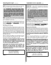
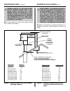
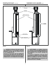
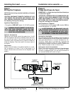
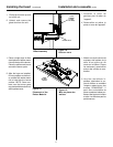
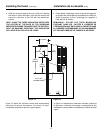
Figure 14 shows the minimum vertical and corresponding
maximum horizontal dimensions of mantels or other
combustible projections above the gas fireplace.
Figure 14
La Figure 14 représente la dimension minimale verticale et
la dimension maximale horizontale correspondante des
habillages ou autres saillies combustibles au-dessus du foyer
à gaz.
Installation de la cassette (suite)
4. Faites glisser l’entourage contre la façade de l’appareil,
en alignant les orifices des coins supérieurs et inférieurs,
droits et gauches, et fixez l’entourage sur l’appareil à
l’aide des vis de fixation.
REMARQUE : PLACEZ LES TROIS MORCEAUX
D’ISOLANT DANS LES CAVITÉS À L’ARRIÈRE DE
L’ENTOURAGE AVANT DE PLACER LA CASSETTE DANS
LA CHEMINÉE PRÉFABRIQUÉE OU EN MAÇONNERIE.
CET ISOLANT EMPÊCHE LE PASSAGE D’AIR FROID.
12" (305mm)
MANTEL
TOP OF UNIT /
LE SOMMET D’UNITÉ
6"
(152mm)
MINIMUM
12"
(305mm)
MINIMUM
1 1/2"
(38mm)