


Special offers from our partners!

Find Replacement BBQ Parts for 20,308 Models. Repair your BBQ today.

24
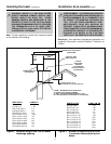
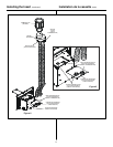
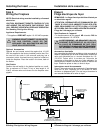
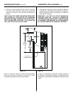
Figure 9.
Standing Pilot Ignition Wiring Diagram
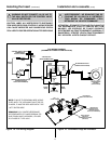
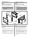
Step 6
Wiring the Fireplace
Installing the Insert (continued)
NOTE: Electrical wiring must be installed by a licensed
electrician.
CAUTION: DISCONNECT REMOTE CONTROLS IF YOU
ARE ABSENT FOR EXTENDED TIME PERIODS. THIS
WILL PREVENT ACCIDENTAL FIREPLACE OPERATION.
For Standing Pilot Ignition Wiring
Appliance Requirements
• This appliance DOES NOT require 110-120 VAC to operate.
WARNING: DO NOT CONNECT 110-120 VAC TO
THE GAS CONTROL VALVE OR THE
APPLIANCE WILL MALFUNCTION AND THE
VALVE WILL BE DESTROYED.
Optional Accessories
Optional fan and remote control kits require that 110-120
VAC be supplied to the factory installed junction box. Run
the cord out the notch in the surround and plug into a
convenient outlet. An electrician may install an outlet box
inside the fireplace. Place the outlet in the lower, back of
the firebox.
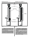
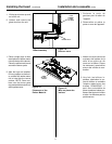
Wall Switch
Position the wall switch in the desired position on a wall.
Run a maximum of 25 feet (7.8 m) or less length of 18
A.W.G. minimum wire and connect it to the fireplace valve
pigtails.
!
Étape 6
Filage électrique du foyer
Installation de la cassette (suite)
REMARQUE : Le filage électrique doit être effectué par
un électricien agréé.
ATTENTION : DÉBRANCHEZ LES COMMANDES À DIS-
TANCE SI VOUS VOUS ABSENTEZ POUR DES PÉRI-
ODES PROLONGÉES. DE CETTE FAÇON, LE FOYER
NE POURRA PAS S’ALLUMER ACCIDENTELLEMENT.
Filage de l’allumage par veilleuse
Spécifications de l’appareil
• Le fonctionnement de cet appareil NE nécessite PAS de
courant électrique de 110-120 VCA.
AVERTISSEMENT: NE BRANCHEZ PAS DE
COURANT ÉLECTRIQUE DE 110-120 VCA À
LA VALVE DE COMMANDE DE GAZ. CELA
ENTRAÎNERAIT UN MAUVAIS FONCTIONNEMENT
DE L’APPAREIL ET LA DESTRUCTION DE LA VALVE.
Accessoires facultatifs
Les ensembles facultatifs de ventilateur et de commande à
distance nécessitent que la boîte de dérivation installée en
usine soit alimentée par un courant électrique de 110-
120 VCA. Faites sortir le cordon par l’encoche de
l’entourage et branchez-le dans une prise adéquate. Un
électricien peut installer une boîte de sortie à l’intérieur du
foyer. Placez les prises en bas, au fond du foyer.
Interrupteur mural de commande
Placez l’interrupteur mural de commande à l’emplacement
voulu sur un mur. Déployez un fil de calibre 18 AWG
minimum ne dépassant pas 7,8 m de long et branchez-le
aux raccords flexibles de la valve du foyer.
!
Figure 9.
Schéma de filage de l’allumage par veilleuse
3/16” PIGGY BACK
CONNECTOR
(CONNECTEUR EN
CASCADE DE 3/16 PO.)
GAS VALVE
(VALVE DE COMMANDE
DE GAZ)
THERMOPILE
ON/OFF ROCKER SWITCH
(
INTERRUPTEUR À BASCULE
MARCHE/ARRÊT)
THERMOCOUPLE
OPTIONAL WALL SWITCH
THERMOSTAT OR REMOTE
(
)
INTERRUPTEUR MURAL, THERMOSTAT
OU COMMANDE À DISTANCE FACULTATIFS