


Special offers from our partners!

Find Replacement BBQ Parts for 20,308 Models. Repair your BBQ today.

16
3
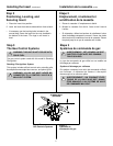
Installing the Insert
Step 1
Installing the Vent System
Vent System Installation Precautions
Before starting installation of vent kits, the installer should
read these instructions and the Vent Kit Instructions to
ensure that a proper vent installation is completed. Consult
your local Building Codes before beginning the Installation.
WARNING: THIS GAS INSERT AND VENT
ASSEMBLY MUST BE VENTED DIRECTLY TO
THE OUTSIDE AND MUST NEVER BE ATTACHED TO
A CHIMNEY SERVING A SEPARATE SOLID FUEL
BURNING APPLIANCE. EACH GAS APPLIANCE
MUST USE A SEPARATE VENT SYSTEM. COMMON
VENT SYSTEMS ARE PROHIBITED.
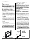
Vent System Approvals
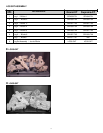
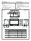
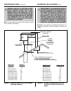
Table 1 and Figure 3 through 6 shows the vent termination
caps and systems approved for use with these models.
Approved vent system terminations are labeled for
identification. 3-inch diameter listed flexible aluminum or
stainless steel gas vent is used for both the incoming
combustion air and exhaust vent pipes. NO OTHER
VENTING SYSTEMS OR COMPONENTS MAY BE USED.
Detailed installation instructions are included with each vent
termination kit and should be used in conjunction with this
manual.
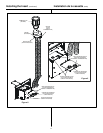
Horizontal Venting
The vent system on this model CANNOT be terminated
horizontally.
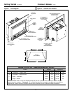
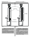
Vertical Venting
The vent pipes MUST be connected to the proper collars on
the unit AND the exhaust vent pipe MUST be connected to
the termination cap or the unit will not operate. The
combustion air vent pipe CAN be connected to the
termination cap or it can terminate inside the chimney. The
bottom opening of the chimney must be sealed around the
vent pipes if the combustion air vent is NOT connected to
the termination cap. Use unfaced fiberglass insulation to
seal around the vent pipes. The insulation may give off an
odor during the first hour of operation. See Figures 4, 5 and 6.
NOTE: The minimum vertical rise (exhaust vent) is 14 feet
and the maximum vertical rise is 50 feet. These dimensions
are measured from the starting collars of the unit to the end
of the last section of vent pipe. See dimension V in Figure 4.
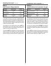
Installation de la cassette
Étape 1
Installation du système d’évacuation
Précautions d’installation du système d’évacuation
Avant de commencer à installer les modules d’évacuation,
l’installateur doit lire ces instructions et celles des modules
d’évacuation afin d’obtenir une installation correcte.
Consultez les codes de construction de votre région avant
de commencer l’installation.
AVERTISSEMENT : CETTE CASSETTE À GAZ ET
CE SYSTÈME D’ÉVACUATION DOIVENT ÉVA-
CUER LES GAZ DE COMBUSTION DIRECTEMENT À
L’EXTÉRIEUR ET NE DOIVENT JAMAIS ÊTRE RAC-
CORDÉS À UNE CHEMINÉE DESSERVANT UN AU-
TRE APPAREIL À COMBUSTIBLE SOLIDE. CHAQUE
APPAREIL À GAZ DOIT UTILISER UN SYSTÈME D’É-
VACUATION DISTINCT. L’UTILISATION DE SYSTÈ-
MES D’ÉVACUATION EN COMMUN EST INTERDITE.
Homologation du système d’évacuation
Le Tableau 1 et les Figures 3 à 6 représentent les capuchons
et les systèmes d’évacuation homologués pour utilisation
avec ces modèles. Les terminaisons de système
d’évacuation homologuées portent une étiquette
d’identification. Des conduits flexibles homologués de 76 mm
de diamètre, en aluminium ou en acier inoxydable, servent
à l’aspiration de l’air de combustion et à l’évacuation des
gaz de combustion. AUCUN AUTRE SYSTÈME OU
ÉLÉMENT D’ÉVACUATION NE PEUT ÊTRE UTILISÉ. Des
instructions d’installation détaillées sont incluses avec
chaque module de terminaison de système d’évacuation et
doivent être utilisées en conjonction avec ce manuel.
Évacuation horizontale
Le système d’évacuation de ce modèle NE PEUT PAS
comporter de terminaison horizontale.
Évacuation verticale
Les conduits DOIVENT être raccordés aux collets corres-
pondants de l’appareil ET le conduit d’évacuation DOIT être
raccordé au capuchon pour que l’appareil puisse fonctionner.
Le conduit d’air de combustion PEUT être raccordé au
capuchon ou aboutir à l’intérieur de la cheminée. L’ouverture
inférieure de la cheminée doit être jointe hermétiquement
aux conduits si le conduit d’air de combustion n’est PAS
raccordé au capuchon. Utilisez l'isolant de fibre de verre
sans revêtement pour assurer l'étanchéité des conduits
d'évacuation. L'isolant peut dégager une odeur pendant la
première heure de fonctionnement du foyer. Voir Figures 4,
5 et 6.
REMARQUE : La longueur verticale (conduit d’évacuation)
doit être comprise entre 4,3 mètres et 15,2 mètres. Cette
dimension est mesurée entre les collets de raccord de
l’appareil et l’extrémité de la dernière section de conduit
d’évacuation. Voir la dimension V sur la Figure 4.
!
!