


Special offers from our partners!

Find Replacement BBQ Parts for 20,308 Models. Repair your BBQ today.
110112-01A
For more information, visit www.desatech.com
For more information, visit www.desatech.com
9
9
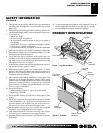
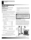
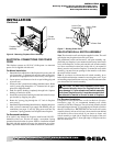
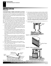
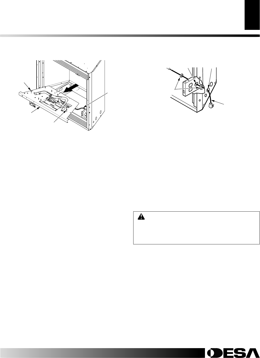
Figure 6 - Removing Fireplace Floor Assembly
Screw
Fireplace Floor
Assembly
Flexible
Gas Line
INSTALLATION
Continued
ELECTRICAL CONNECTIONS FOR POWER
CORD
This fireplace operates on 120 VAC, 60 Hz power. An electrical
power cord is supplied with this unit.
For Mantel Installation
1. Determine from which side of the fireplace the power cord will
exit. Locate the 1.5" diameter hole near the center of floor sup-
port bracket on appropriate side of lower cavity (see Figure 7).
2. Locate power cord. Remove wire tie or tape holding plug end
of power cord.
3. Power cord has 2 plastic hole bushings threaded onto it. Route
cord's 3-prong plug through the 1.5" diameter hole in appro-
priate floor support bracket.
4. Push first plastic bushing completely through hole. Squeeze
bushing as needed to do this.
5. Install the second plastic bushing into the hole in the floor sup-
port bracket by snapping into place.
6. Route the 3-prong plug through the 1.5" hole in fireplace
outer casing.
7. Install the first plastic bushing into this hole by snapping into place.
8. After you have connected to gas supply and checked your gas
connections (see pages 15 and 16), plug power cord into any
convenient 3-prong grounded wall receptacle near fireplace.
For Recessed Installation
If an outlet is not installed in fireplace, install model GA3555 -
Outlet Kit with Cover. This kit will supply a convenient 3-prong
grounded electrical outlet for power. Refer to installation manual
provided with this optional accessory for instructions on wiring.
Note:
A qualified installer must make all electrical connections.
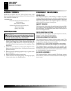
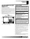
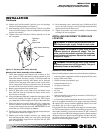
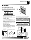
Figure 7 - Routing Power Cord
Power Cord
Bushings
Hole in Floor
Support Bracket
Hole in Outer
Casing
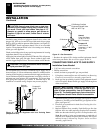
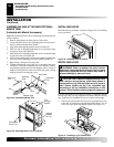
RELOCATING WALL SWITCH ASSEMBLY
Note:
The decorative wall switch plate supplied is white. The wall
switch plate may be painted to match your decor.
The push-button switch and decorative wall plate assembly sup-
plied with your fireplace is pre-mounted at the factory in the lower
cavity of the fireplace. You may relocate this wall switch assembly
to a more convenient location such as the side of your mantel or
directly onto the wall near the fireplace. To mount the wall switch
assembly, you must first cut openings in the mantel or wall where
the switch will be located.
Note:
If you choose to relocate the wall switch assembly, do so
before final installation into a mantel or recessing into a wall. If you
are installing an optional blower accessory, install it at the same time
you relocate the wall switch assembly.
For Recessed Installation
If fireplace is to be recessed into a wall (see Built-In Fireplace
Installation, page 15), we recommend mounting wall switch
assembly to left side of fireplace. The wall switch assembly should
be mounted approximately 12" from left edge of fireplace, and less
than 60" from the floor.
IMPORTANT:
Do not locate wall switch
assembly directly in front of wall stud - there must be room behind
wall board for wires from switch. If you choose to locate wall
switch assembly to right side of fireplace, the length of the cord
restricts you to less than 6" from right edge of fireplace and less
than 48" from floor.
CAUTION: The wall switch assembly must never
be mounted directly above the fireplace where heat
may damage it. If you relocate wall switch assembly
from lower fireplace cavity, it must be mounted either
on side wall of mantel or on wall to side of fireplace.
INSTALLATION
Removing Fireplace Screen And Floor Assembly (Cont.)
Electrical Connections for Power Cord
Relocating Wall Switch Assembly
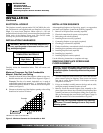
Screw