


Special offers from our partners!

Find Replacement BBQ Parts for 20,308 Models. Repair your BBQ today.
110112-01A
For more information, visit www.desatech.com
For more information, visit www.desatech.com
22
CLEANING AND MAINTENANCE
Cleaning Burner Injector Holder (Cont.)
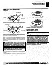
Logs
SPECIFICATIONS0
LOGS
• If you remove logs for cleaning, refer to Installing Logs, pages
16 and 17, to properly replace logs.
• Replace log(s) if broken or chipped (dime-sized or larger).
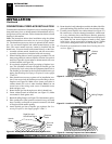
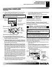
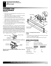
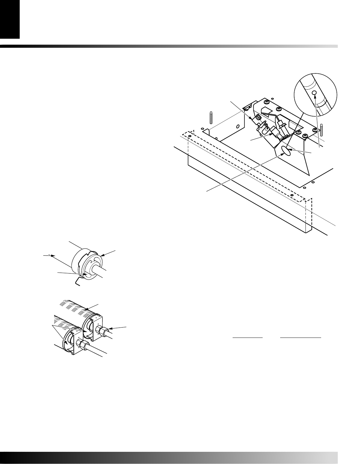
Figure 47 - Cleaning Pilot Air Inlet Hole
Pilot Air
Inlet Hole
Pilot
Assembly
Pilot Bracket
1. Shut off the unit, including the pilot. Allow the unit to cool for
at least thirty minutes.
2. Inspect burners, pilot, and primary air inlet holes on injector
holder for dust and dirt (see Figures 45 and 46).
3. Blow air through the ports/slots and holes in the burners.
4. Check the injector holders located at the end of the burner tubes
again. Remove any large particles of dust, dirt, lint, or pet hair
with a soft cloth or vacuum cleaner nozzle.
5. Blow air into the primary air holes on the injector holders.
6. In case any large clumps of dust have now been pushed into
the burner repeat steps 3 and 4.
Clean the pilot assembly also. A yellow tip on the pilot flame
indicates dust and dirt in the pilot assembly. There is a small pilot
air inlet hole about two inches from where the pilot flame comes out
of the pilot assembly (see Figure 47). With the unit off, lightly blow
air through the air inlet hole. The access hole for propane/LP pilot
is on the front of the burner carriange as shown in Figure 47. The
access hole for natural pilot is behind the pilot bracket on the top of
burner carriage (see Figure 47). You may blow through a drinking
straw if compressed air is not available.
CLEANING AND
MAINTENANCE
Continued
SPECIFICATIONS
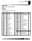
Btu (Variable) 20,000/33,000
Type Gas Natural: VTGF33NRA
Propane/LP: VTGF33PRA
Ignition Electronic (Automatic)/Piezo (Manual)
Natural Gas Propane/LP Gas
Manifold Pressure 3.5" W.C. 8.0" W.C.
Inlet Gas Pressure (in. of water)
Maximum 10.5" 14"
Minimum* 5" 11"
Shipping Weight 78 lbs. 78 lbs.
* For input adjustment
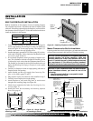
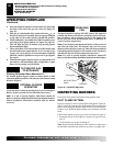
Figure 45 - Injector Holder On Outlet Burner Tube - Rear Burner
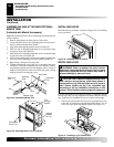
Figure 46 - Injector Holder On Outlet Burner Tubes - Front and
Middle Burners
Primary Air
Inlet Holes
Burner Tube
Injector
Holder
Ports/Slots
Injector Holder
Primary Air
Inlet Holes
Access Hole For
Cleaning PIlot