


Special offers from our partners!

Find Replacement BBQ Parts for 20,308 Models. Repair your BBQ today.
110112-01A
For more information, visit www.desatech.com
For more information, visit www.desatech.com
11
11
INSTALLATION
Relocating Wall Switch Assembly (Cont.)
Installing Gas Piping to Fireplace Location
INSTALLATION
Continued
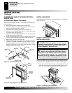
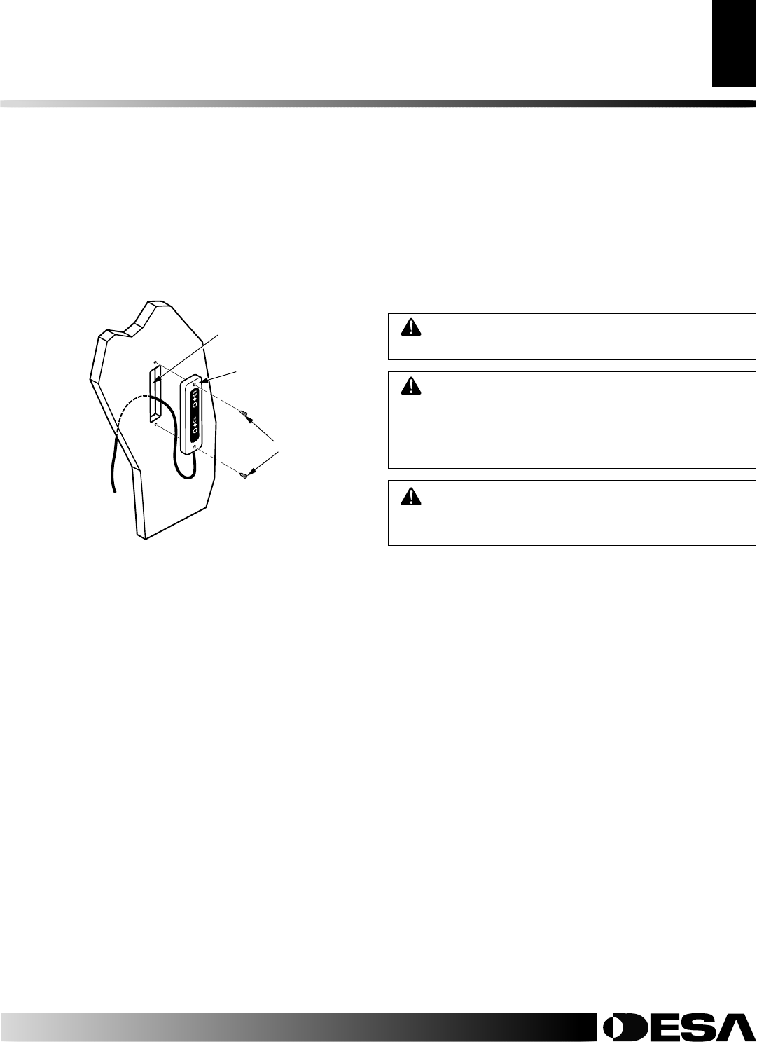
16. Position wall switch assembly vertically over wall openings
with decal lettering upright (see Figure 13).
17. Insert mounting screws, removed in step 2 of Relocating Wall
Switch Assembly on pages 9 and 10, through holes in wall plate
and into wall anchors.
18. Tighten screws until wall plate is firmly attached to wall. Do
not overtighten.
Mounting Wall Switch Assembly to Side of Mantel
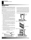
7. Create three openings in the mantel wall according to Tem-
plate 2, page 33. This is best done by making a pattern to work
with on the mantel. Carefully cut page 33/34 from manual and
tape paper template vertically onto mantel wall at preferred
location. Pierce the paper at the centers of the 2 holes with a
nail or sharp pencil, leaving a mark on the wall. Do the same
at centers of the four circles near the corners of the rectangle.
8. Remove paper template from mantel wall.
9. Drill 1/8" pilot holes at each mark for top and bottom screw
holes. Drill 3/8" holes at each mark for centers of four circles
near corners of rectangle.
10. Using a straight edge and pencil, connect the outer edges of the 4
holes for the rectangle (see Figure 10, page 10). This will give
you cutting lines for the rectangle you will cut in the mantel wall.
11. Using a keyhole saw, hack saw blade, drill, file, or other suit-
able tool, carefully cut out the rectangular opening.
Note:
The
corners of the rectangle may be round.
IMPORTANT:
Do not
exceed the size of the rectangle on template.
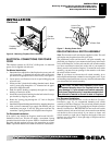
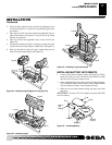
12. Carefully pass wall switch assembly through rectangular open-
ing from inside mantel (see Figure 13).
13. Position wall switch assembly vertically over opening with
decal lettering upright. Make sure wires freely pass through
wall without binding. Align holes in wall plate with 1/8" pilot
holes in mantel wall.
14. Drive mounting screws, removed in step 2 of Relocating Wall
Switch Assembly on pages 9 and 10, through wall plate holes
and into pilot holes in mantel wall.
15. Tighten screws until wall switch assembly is firmly attached
to mantel. Do not overtighten.
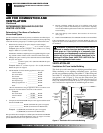
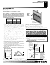
Figure 13 - Securing Wall Switch Assembly
Screws
Wall Switch Assembly
Opening in
Wall or
Mantel Wall
WARNING: A qualified service person must con-
nect fireplace to gas supply. Follow all local codes.
WARNING: For natural gas units, never connect
fireplace to private (non-utility) gas wells. This gas is
commonly known as wellhead gas.
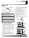
INSTALLING GAS PIPING TO FIREPLACE
LOCATION
WARNING: For propane/LP units, never connect
fireplace directly to propane/LP supply. This fire-
place requires an external regulator (not supplied).
Install the external regulator between the heater and
propane/LP supply.
Installation Items Needed
Before installing fireplace, make sure you have the items listed below.
• external regulator (supplied by installer, for propane/LP units only)
• piping (check local codes)
• sealant (resistant to propane/LP gas)
• equipment shutoff valve *
• test gauge connection *
• sediment trap
• tee joint
• pipe wrench
• approved flexible gas line with gas connector (if allowed by lo-
cal codes) (not provided)
* A CSA design-certified equipment shutoff valve with 1/8" NPT
tap is an acceptable alternative to test gauge connection. Purchase
the optional CSA design-certified equipment shutoff valve from
your dealer. See Accessories, pages 30 and 31.
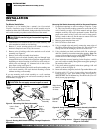
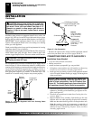
For propane/LP units, the installer must supply an external regula-
tor. The external regulator will reduce incoming gas pressure. You
must reduce incoming gas pressure to between 11 and 14 inches of
water. If you do not reduce incoming gas pressure, heater regulator
damage could occur. Install external regulator with the vent point-
ing down as shown in Figure 14, page 12. Pointing the vent down
protects it from freezing rain or sleet.