


Special offers from our partners!

Find Replacement BBQ Parts for 20,308 Models. Repair your BBQ today.
110112-01A
For more information, visit www.desatech.com
For more information, visit www.desatech.com
12
INSTALLATION
Installing Gas Piping to Fireplace Location (Cont.)
Connecting Fireplace To Gas Supply
INSTALLATION
Continued
WARNING: Use pipe joint sealant that is resistant
to liquid petroleum (LP) gas.
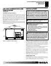
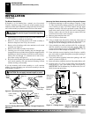
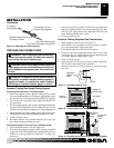
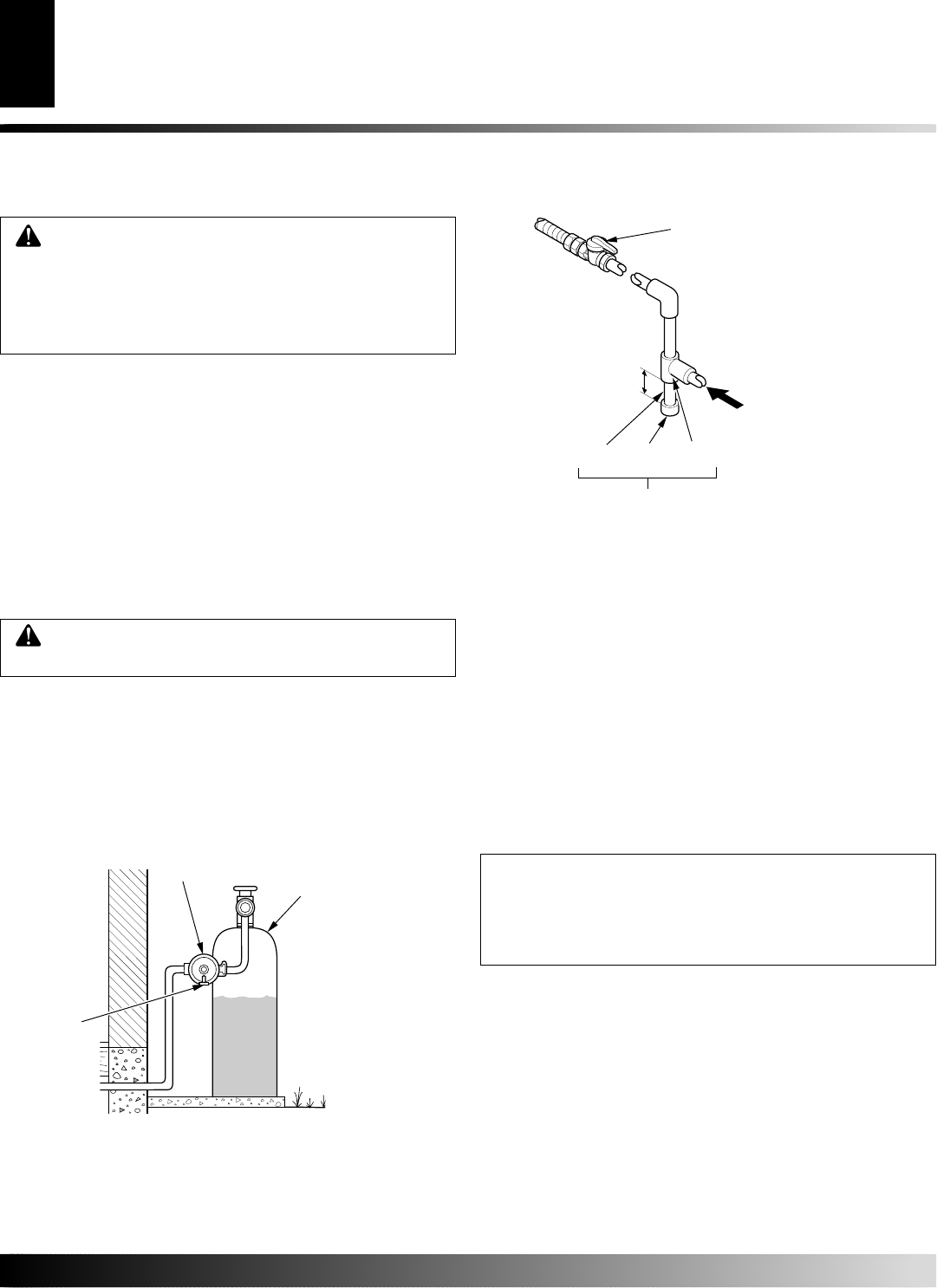
We recommend that you install a sediment trap in supply line as
shown in Figure 15. Locate sediment trap where it is within reach for
cleaning. Install in piping system between fuel supply and fireplace.
Locate sediment trap where trapped matter is not likely to freeze. A
sediment trap traps moisture and contaminants. This keeps them
from going into fireplace gas controls. If sediment trap is not
installed or is installed wrong, fireplace may not run properly.
Installation must include an equipment shutoff valve, union, and
plugged 1/8" NPT tap. Locate NPT tap within reach for test gauge
hook up. NPT tap must be upstream from fireplace (see Figure 14).
IMPORTANT:
Install equipment shutoff valve in an accessible
location. The equipment shutoff valve is for turning on or shutting
off the gas to the appliance.
Check your building codes for any special requirements for locating
equipment shutoff valve to fireplaces.
Apply pipe joint sealant lightly to male NPT threads. This will prevent
excess sealant from going into pipe. Excess sealant in pipe could
result in clogged fireplace valves. Never use sealant on flare threads.
CAUTION: Use only new, black iron or steel pipe.
Internally-tinned copper tubing may be used in cer-
tain areas. Check your local codes. Use pipe of 1/2"
diameter or greater to allow proper gas volume to
fireplace. If pipe is too small, undue loss of volume
will occur.
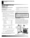
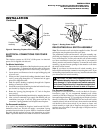
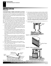
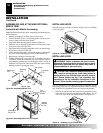
Figure 14 - External Regulator with Vent Pointing Down
(Propane/LP Gas)
Propane/LP
Supply Tank
External
Regulator
Vent
Pointing
Down
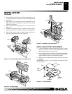
Figure 15 - Gas Connection
* Purchase the optional CSA design-certified equipment shutoff
valve from your dealer. See Accessories, pages 30 and 31.
Natural
From Gas Meter
(5" W.C. to 10.5"
W.C. Pressure)
Propane/LP
From External
Regulator (11" W.C.
to 14 " W.C.
Pressure
CSA Design-Certified
Equipment Shutoff Valve
With 1/8" NPT Tap*
3" Minimum
Installation Items Needed
• 5/16" hex socket wrench or nut-driver
• Phillips screwdriver
• sealant (resistant to propane/LP gas, not provided)
1. If fireplace screen and floor are still installed, see Removing
Fireplace Screen and Floor Assembly, pages 8 and 9.
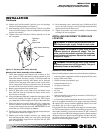
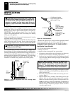
2. Route gas line (provided by installer) from equipment shutoff
valve to fireplace. Route flexible gas supply line through one
of the access holes.
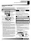
CONNECTING FIREPLACE TO GAS SUPPLY
3. Attach the flexible gas line to gas supply (see Figure 16). Check
tightness of flexible gas line attached to gas regulator of fire-
place (see Figure 16).
4. Check all gas connections for leaks. See Checking Gas Con-
nections, page 13.
5. Replace fireplace floor assembly. Feed flexible gas line into
fireplace base area while replacing fireplace floor assembly.
Make sure the entire flexible gas line is in fireplace base area.
Note:
Be careful of wires and components on underside of
fireplace floor. Reattach fireplace floor assembly with screws
removed in step 3 of Removing Fireplace Screen and Floor
Assembly, pages 8 and 9.
NOTICE: Most building codes do not permit con-
cealed gas connections. A flexible gas line is pro-
vided to allow accessibility from the fireplace (see
Figure 16). The flexible gas supply line connection to
the equipment shutoff valve should be accessible.
Sediment Trap
Pipe Cap Tee
Nipple Joint