


Special offers from our partners!

Find Replacement BBQ Parts for 20,308 Models. Repair your BBQ today.

110112-01A
For more information, visit www.desatech.com
For more information, visit www.desatech.com
15
15
INSTALLATION
Built-In Fireplace Installation
INSTALLATION
Continued
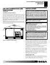
BUILT-IN FIREPLACE INSTALLATION
Built-in installation of this fireplace involves installing fireplace
into a framed-in enclosure. This makes the front of fireplace flush
with wall. If installing a mantel above the fireplace, you must follow
the clearances shown in Figure 27. Follow the instructions below to
install the fireplace in this manner.
Actual Framing
Height 32
3
/
8
" 33"
Front Width 34
5
/
16
" 35
1
/
2
"
Depth 16
11
/
16
" 17
3
/
4
"
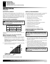
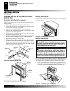
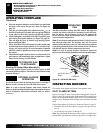
1. Frame in rough opening. Use dimensions shown in Figure 24
for the rough opening. If installing in a corner, use dimensions
shown in Figure 25 for the rough opening. The height is 33"
which is the same as the wall opening above.
2. Install and properly ground GA3555, three-prong 120 volt elec-
trical outlet, in fireplace. Follow instructions included in kit (see
Accessories, pages 30 and 31).
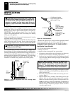
3. If not already completed, install gas piping to fireplace loca-
tion. This installation includes an approved flexible gas line
(if allowed by local codes) after the equipment shutoff valve.
The flexible gas line must be the last item installed on the gas
piping. See Installing Gas Piping to Fireplace Location, pages
11 and 12.
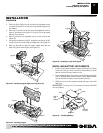
4. Carefully set fireplace in front of rough opening with back of
fireplace inside wall opening.
5. Attach flexible gas line to gas supply. See Connecting Fire-
place to Gas Supply, pages 12 and 13.
6. Plug electrical cord(s) into electrical outlet installed in step 2.
7. Carefully insert fireplace into rough opening.
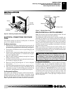
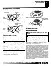
8. Attach fireplace to wall studs using nails or wood screws
through holes in nailing flange (see Figure 26).
9. Check all gas connections for leaks. See Checking Gas Con-
nections, pages 13.
10. Install brass trim. See Assembling and Attaching Optional
Brass Trim, page 16.
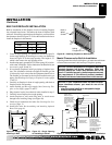
35
1
/
2
"
17
3
/
4
"
33"
39
3
/
8
"
27
7
/
8
"
55
5
/
8
"
35
1
/
2
"
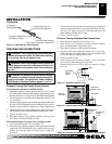
Figure 24 - Rough Opening for
Installing in Wall
Figure 25 - Rough Opening
for Installing in Corner
Figure 26 - Attaching Fireplace to Wall Studs
Nailing
Flanges
Nails or
Wood
Screws
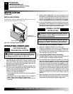
Mantel Clearances for Built-In Installation
If placing mantel above built-in fireplace, you must meet minimum
clearance between mantel shelf and top of fireplace opening.
NOTICE: Surface temperatures of adjacent walls and
mantels become hot during operation. Walls and
mantels above the firebox may become hot to the
touch. If installed properly, these temperatures meet
the requirement of the national product standard.
Follow all minimum clearances shown in this manual.
NOTICE: If your installation does not meet the mini-
mum clearances shown, you must do one of the
following:
• raise the mantel shelf to an acceptable height
• remove the mantel shelf
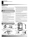
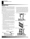
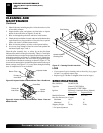
Figure 27 - Minimum Mantel Clearances for Built-In Installation
Supplied Firebox
Hood Must Be
Used at All Times
Wire-mesh
Screen
Firebox
Noncombustible
Material May
Project Off this
Surface above
the Firebox Hood
Mantel Shelf
13" 16" 19" 21"
2
1
/2
"
6"
8"
10"
Note:
All vertical
measurements are
from top of fireplace
hood opening to bottom
of mantel shelf.
These minimum
clearances replace any
other recommended
clearances supplied with
your ANSI Z21.11.2
approved gas logs.
Wall board or facing
material (above
firebox) may be of
combustible material,
including decorative
mantel ornaments or
other similar projec-
tions off of the facing
material.
Framing
Material