


Special offers from our partners!

Find Replacement BBQ Parts for 20,308 Models. Repair your BBQ today.
5
www.desatech.com
117437-01
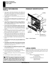
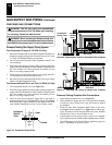
Carton Tray
Corner Post
Log Carton
Glass Panel
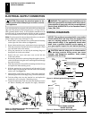
PRE-INSTALLATION PREPARATION
Clearances
Framing and Finishing
PRE-INSTALATION PREPARATION
Continued
CLEARANCES
Minimum clearances to combustibles for the fi replace are as follows:
Back, and sides 0” (0 mm)
Perpendicular walls 10” (254 mm)
Floor 0” (0 mm)
Ceiling to louver opening 36” (914 mm)
Front 36” (914 mm)
Top 0” (0 mm)
B-Vent Surfaces 1” (26 mm) (See venting instructions
for specifi cs on vent clearances.)
Mantel Clearances (See - Mantel Clearances for specifi c
clearances to combustible mantels.)
Combustible material with a maximum thickness of 5/8” (16 mm)
may be fl ush with the top and sides of the front face of the fi replace.
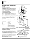
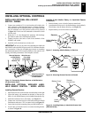
PACKAGING AND REMOVAL
The (V)CB36 vented decorative gas fi replaces are packaged with:
- one box containg a 4-log set located on the burner in the fi rebox.
- one bag containing the owner’s manual with installation
instructions, operator’s guide, and warranty information.
- one bag of glowing ember material.
- one bag of vermiculite hearth treatments.
Remove the shrinkwrap securing the 2 carton trays to the unit.
Lift the top carton tray off and remove the four corner posts.
Discard the bottom tray once the unit is moved into position.
Note:
To prvent damage to ceramic logs and glass panels you
may want to remove them before positioning and framing the unit.
To access fi rebox, see Hearth Access and Assembly, page ##.
Figure 4 - Unpacking Fireplace
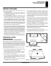
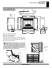
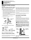
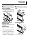
FRAMING AND FINISHING
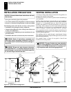
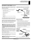
Figure 5 shows typical framing of this fi replace. Figure 6 shows
framing for corner installation. All minimum clearances must be met.
For overall unit dimensions, framing allowances, and vent collar
locations, see Unit Dimensions, Figure 7 on page 6.
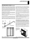
For available accessories for this fi replace, see Accessories on page
33. If you are using a seperate combustible mantel piece, refer to
Figures 8 and 9 for proper height and clearances. You can install a
noncombustible mantel at any height above the fi replace opening.
Note: Non-combustible mantels may discolor!
Figure 5 - Framing Clearances for Flush, Wall Installation
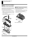
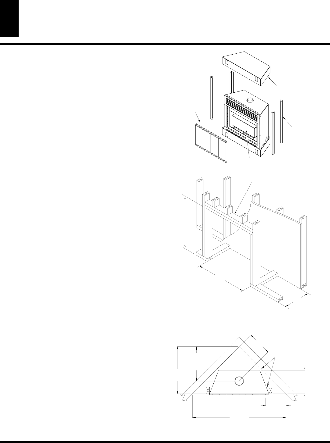
Figure 6 - Framing Clearances for Corner Installation
14 3/4" (375 mm)
36 1/4" (921 mm)
36"
(914 mm)
2 x 4 FLAT
HEADER
FOR 1" OF CLEARANCE
AT THE SIDES AND BACK
OF THE FIREPLACE
IS ALSO PERMITTED AT
HOWEVER, 0" CLEARANCE
ALL SIDES WHEN FRAMED
THESE DIMENSIONS ALLOW
21" (533 mm)
TO CENTER OF
TOP VENT
14 3/4"
(375 mm)
TO NAILING
FLANGES
56 3/4"
(1441 mm)
12 1/4"
(311 mm)
TO
OPENING
28 5/8"
(727 mm)
14 3/4"