


Special offers from our partners!

Find Replacement BBQ Parts for 20,308 Models. Repair your BBQ today.
19
www.desatech.com
117437-01
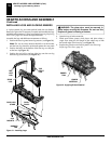
INSPECTING BURNERS
Pilot Assembly
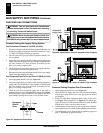
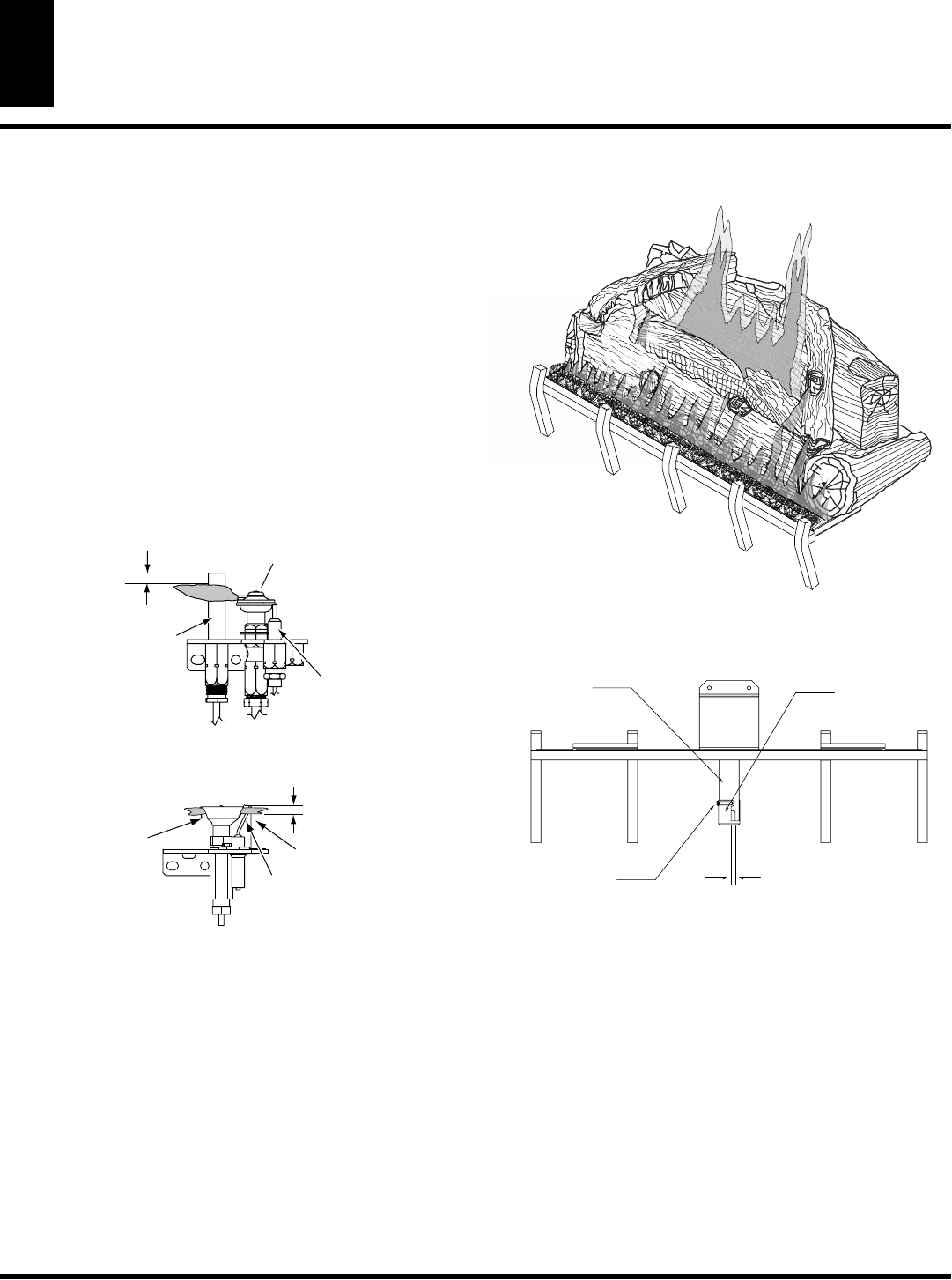
Burner Flame Pattern
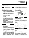
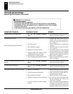
Figure 40 -
Typical Flame Pattern
INSPECTING BURNERS
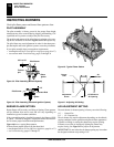
BURNER FLAME PATTERN
Burner fl ames will be steady; not lifting or fl oating. Flame patterns
will be different from unit to unit and will vary depending on
installation type and weather conditions.
If the vent confi guration is installed incorrectly, the fl ames will lift
or “ghost”. This can be dangerous. Inspect the fl ames after installa-
tion to ensure proper installation and performance.
Figure 40 shows a typical fl ame pattern.
If burner fl ame pattern differs from that described:
• turn fi replace off (see To Turn Off Gas to Appliance, page 16 or 17)
• see Troubleshooting, pages 21 through 25
Check pilot fl ame pattern and burner fl ame patterns often.
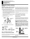
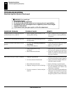
PILOT ASSEMBLY
The pilot assembly is factory preset for the proper fl ame height
Alterations may have occurred during shipping and handling. Call
a qualifi ed service person to readjust the pilot if necessary.
The position and pattern of the pilot fl ames in relation to the sens-
ing devices should be as shown in Figures 38 and 39 respectively.
The pilot fl ame may need adjustment in order for the thermocou-
ple, thermopile and/or the ignition system to sense the pilot fl ame.
If your pilot assembly does not meet these requirements:
• turn fi replace off (see To Turn Off Gas to Appliance, page 16 or17)
• see sections under Troubleshooting, pages 32 through 36
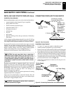
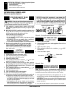
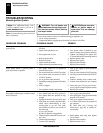
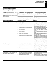
Pilot Burner
Ignitor
Sensor Rod
1/4"
Figure 39 -
Pilot Assembly (Electronic Ignition System)
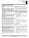
Pilot Burner
3/8" to 1/2"
Thermo-
pile
Piezo
Ignitor
Figure 38 -
Pilot Assembly (Millivolt System)
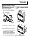
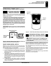
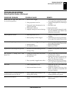
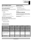
1/8" Minimum
Air Opening
Adjustment
Screw
Burner
Tube
Air
Shutter
Figure 41 -
Adjusting Air Setting
AIR ADJUSTMENT SETTING
The main burner air shutter opening is factory set to the following:
1/8" - Natural Gas
3/4" - LP / Propane Gas
The air shutter may require adjustment depending on the altitude,
venting condition, burner operation and general fl ame appearance.
If fl ames are lifting or sooting the shutter may require opening.
If fl ames are too blue or improperly lighting the shutter may
require closing. See Figure 41 for proper air adjustment.
IMPORTANT:
Do not reduce the air shutter opening any lower than
the designed minimum stop setting of 1/8"