


Special offers from our partners!

Find Replacement BBQ Parts for 20,308 Models. Repair your BBQ today.

9
www.desatech.com
117437-01
NOTICE: This appliance is equipped with a vent safety
shutoff switch which will shut down the appliance in
case of a venting problem. Do not bypass the vent
safety shutoff
switch. If the appliance should
shut
down, have a qualifi ed installer, service agency, or
your gas supplier inspect the vent before operating.
ELECTRICAL SUPPLY CONNECTION
WIRING DIAGRAMS
ELECTRICAL SUPPLY CONNECTION
CAUTION:
Disconnect the electrical power to the
supply circuit before attempting to connect or service
this appliance.
WARNING:
This appliance, when installed must be
electrically grounded in accordance with local code or
in the absence of local code, with the current National
Electric Code, ANSI/NFPA 70, or the Canadian Electric
Code, CSA C22.1.
J-BOX WITH
J-BOX WITH
RECEPTACLE
RECEPTACLE
J-BOX
J-BOX
COVER w/
COVER w/
STRAIN RELIEF
STRAIN RELIEF
J-BOX COVER
J-BOX COVER
SCREW - TAB
SCREW - TAB
RETAINER
RETAINER
J-BOX
J-BOX
COVER w/
COVER w/
STRAIN RELIEF
STRAIN RELIEF
ROMEX
ROMEX
CABLE
CABLE
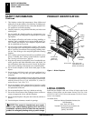
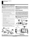
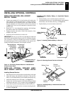
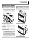
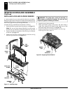
Figure 13 -
Relocating Junction Box Receptacle and
Electrical Supply Connection
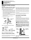
A pre-wired junction box receptacle with strain relief is provided on the
right side of the cabinet for hard wiring the unit to a 15 Amp, 120VAC,
60Hz grounded branch circuit. If the installation demands that the
electrical supply be connected from the left side, the entire receptacle
box can be relocated to the left side by following these instructions:
Note:
If you do not need to relocate the junction box, to connect the
electric supply follow steps 8 through 11 only:
1. Remove the 2 screws and outer cover with strain relief bushing
on the right side of the cabinet (see Figure 13).
2. Remove inner retaining screw on the junction box mounting tab.
3. Slide the junction box up until the screw mounting tab is lined
up to the notch in the outer cabinet.
4. Swing the junction box out and slip the retaining fl ange out
through the slot in the outer cabinet.
5. Remove the two screws and outer cover on the left side
of the outer cabinet.
6. Reinsert the junction box retaining fl ange through the slot now
on the left side and swing the screw mounting tab back through
the notch as before.
7. Slide the junction box down till the mounting tab holes line up
and replace the inner retaining screw.
8. With the junction box cover removed, pull the end of 3-wire
Romex supply line through the universal strain relief bushing
on the cover. (see Figure 13).
9. Strip back the outer Romex to about 4” and connect the black,
white and green wires accordingly using 3 wire nut connectors.
10. Tuck the tailing wires into the junction box and replace the
junction box cover using the 2 remaining screws.
11. Tighten the adjustment on the universal stran bushing to secure
the Romex sheathing and complete the supply connection.
CAUTION: label all wires prior to disconnection
when servicing controls. Wiring errors can cause
improper and dangerous operation. Verify proper
operation after servicing.
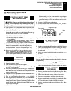
WIRING DIAGRAMS
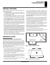
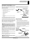
Figure 14 -
Millivolt Ignition Wiring Diagram
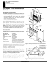
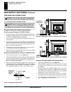
Figure 15 -
Electronic Ignition Wiring Diagram
MILLIVOLT WIRING DIAGRAM
SUPPLY
INCOMING
MAIN GAS
BURNER
PILOT
THERMOPILE
EXTERNAL WIRING USE ONLY CLASS 2
THERMOSTAT WIRE 18 GA. RED/WHITE
WALL SWITCH / REMOTE RECEIVER
TH
TP
TH/TP
WHITE
EQUIVALENT OR HIGHER RATING
REPLACE FACTORY WIRING WITH 105°C
RED
TO 120V
CONNECT
DO NOT
HIGH LIMIT
SWITCH
N
O
T
O
L
P
F
F
O
I
NC
EV2
EV1
BLACK
BLACK
BLACK
GAS VALVE
HIGH LIMIT
SWITCH
NC
PILOT
BURNER
IGNITOR
ORANGE
RED
RED
BLUE
WHITE
BLACK
TRANSFORMER
GROUND
24 VAC
MODULE
IGNITION CONTROL
BLUE
GREEN
120 VAC
ELECTRONIC IGNITION
WIRING DIAGRAM
IGNITION MODULE