


Special offers from our partners!

Find Replacement BBQ Parts for 20,308 Models. Repair your BBQ today.
12
www.desatech.com
117437-01
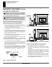
Installation Items Needed
Before installing fi replace, make sure you have the items listed below:
• external regulator (when Propane/LP gas is supplied)
• piping (check local codes)
• sealant (resistant to propane/LP gas)
• equipment shutoff valve *
• test gauge connection *
• sediment trap
• tee joint
• pipe wrench
• approved fl exible gas line with gas connector (if allowed by
local codes)
* A CSA design-certifi ed equipment shutoff valve with 1/8” NPT tap
is an acceptable alternative to test gauge connection. Purchase the
CSA design-certifi ed equipment shutoff valve fromyour retailer.
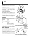
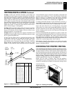
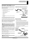
For propane/LP connection only, the installer must supply an external
regulator. You must reduce incoming gas pressure to between 11 and
14 inches of water column. If you do not reduce incoming gas pressure,
fi replace regulator damage could occur. Install external regulator
with the vent pointing down as shown in Figure 22, page 11.
Pointing the vent down protects it from freezing rain or sleet.
GAS SUPPLY AND PIPING
Continued
GAS SUPPLY AND PIPING (Cont)
Installing Gas Piping to Fireplace (Cont.)
Connecting Fireplace to Gas Supply
CAUTION:
Use only new, black iron or steel pipe.
Internally-tinned copper tubing may be used in cer-
tain areas. Check your local codes. Use pipe of 1/2”
inside diameter or greater to allow proper gas volume
to fi replace. If pipe is too small, undue loss of volume
will occur.
WARNING:
Use pipe joint sealant that is resistant
to liquid petroleum (LP) gas.
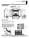
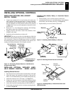
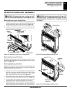
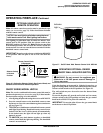
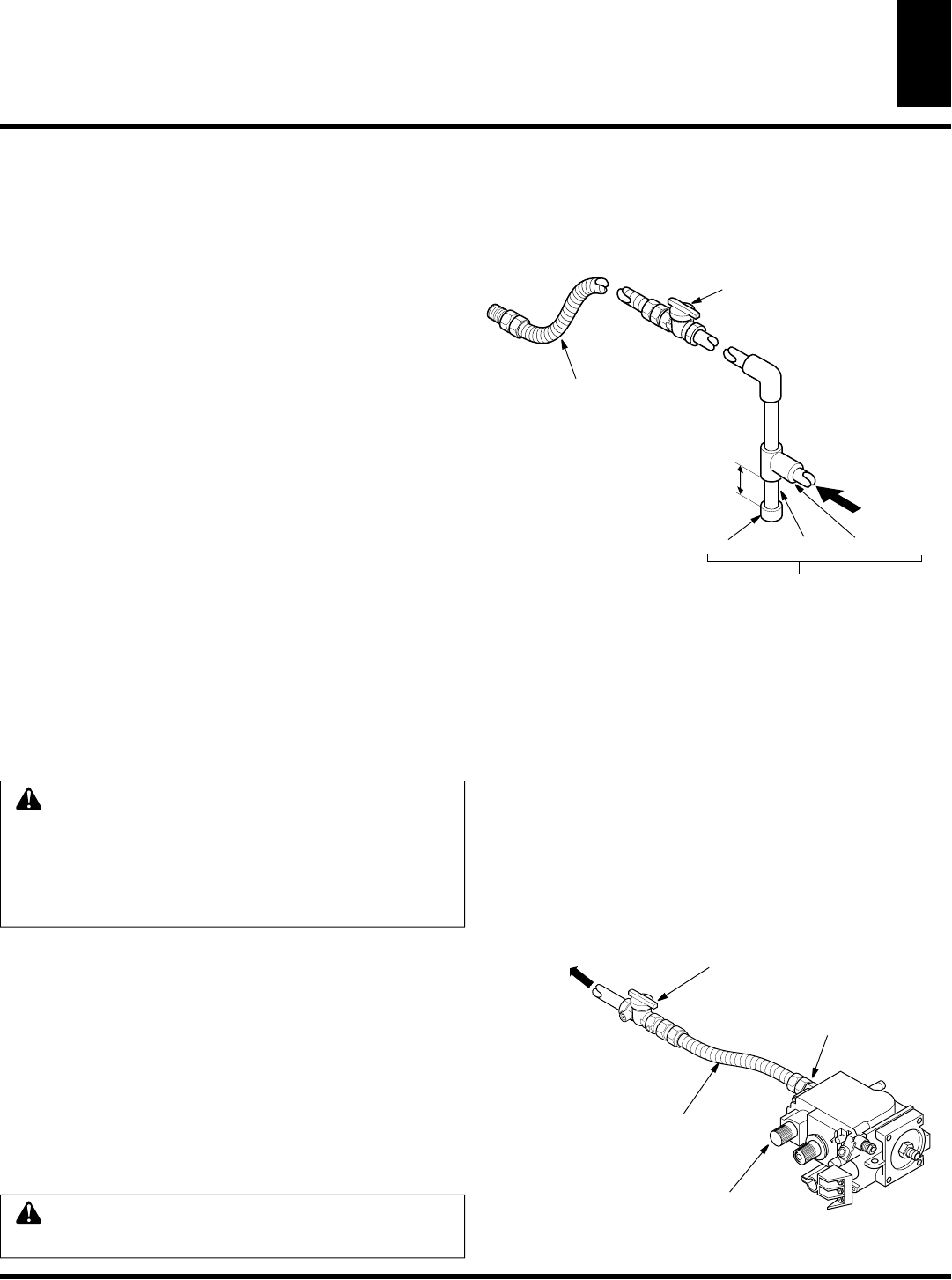
Installation must include an equipment shutoff valve, union and
plugged 1/8” NPT tap. Locate NPT tap within reach for test gauge
hook up. NPT tap must be upstream from fi replace (see Figure 23).
IMPORTANT:
Install main gas valve (equipment shutoff valve) in
an accessible lcation. The main gas valve is for turning on or
shutting off the gas to the appliance.
Check your building codes for any special requirements for locating
equipment shutoff valve to fi replaces.
Apply pipe joint sealant lightly to male NPT threads. This will
prevent excess sealant from going into pipe. Excess sealant in pipe
could result in clogged fi replace valves.
CSA Design-Certified
Equipment Shutoff Valve
with 1/8" NPT Tap*
3" Minimum
Approved Flexible
Gas Line
Cap Pipe Nipple Tee Joint
Sediment Trap/Drip Leg
Natural - From
Gas Meter (5.5"
W.C. to 10.5"
W.C. Pressure)
Propane/LP
From External
Regulator (11"
W.C. to 14"
W.C. Pressure)
Figure 23 -
Gas Connection
Installation Items Needed
• 3/4” and a 7/8” open end wrench or adjustable wrench
• sealant (resistant to propane/LP gas, not provided)
1. Remove lower louver door panel by lifting up unit disengaged
and swing forward and out of the locating slots at the bottom.
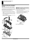
2. Route fl exible gas line (provided by installer) from equipment
shutoff valve to fi replace. Route fl exible gas supply line through
one of the access holes on each side of the fi replace cabinet.
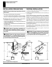
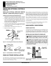
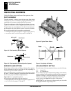
3. Attach fl exible gas line from gas supply to the 1/2” fl are fi tting
provided on the control valve (see Figure 24).
4. Check all gas connections for leaks. See Checking Gas Con-
nections, page 13.
Flexible Gas Line
Do NOT Kink
Equipment
Shutoff Valve
To Gas Supply
(Natural)
To External
Regulator
(Propane/LP)
1/2” Flare Fitting
Control Valve
Figure 24 -
Connecting Flexible Gas Line to Millivolt Valve
CONNECTING FIREPLACE TO GAS SUPPLY
INSTALLING GAS PIPING TO FIREPLACE (Cont.)