


Special offers from our partners!

Find Replacement BBQ Parts for 20,308 Models. Repair your BBQ today.
4
www.desatech.com
117437-01
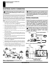
PRODUCT FEATURES
PRE-INSTALLATION PREPARATION
Location and Space Requirements
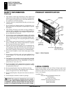
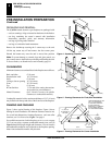
PRODUCT FEATURES
These are a few facts that can help you understand and enjoy your
vented decorative fi replace:
• The (V)CB36(N,P)(E) series of vented decorative fi replaces may
be recessed into an exterior chase, an interior fl ush wall enclosure
or a framed-in corner
installation.
• Models (V)CB36(N,P) are equipped with a millivolt gas control
system that does not require electricity to operate. A piezo ignitor
is provided to light the pilot without using matches or lighters.
• Models (V)CB36(NE/PE) are equipped with an electronic ignition
system that requires 120VAC to operate. An electrode ignitor
automatically lights the pilot fl ame when the fi replace is turned on.
• These fi replaces can accept any approved 4” B-Type venting
system and must be terminated vertically through the roof
using a listed type vent cap only. See venting instructions on
pages # and # for proper venting requirements.
• These vented fi replaces require indoor air for combustion and must
be installed in a room of suffi cient size to provide adequate fresh air
for safe and proper operation. The room intended for installation must
be of suffi cient size to meet the requirements for an unconfi ned space
as defi ned in the
National Fuel Gas Code, ANSI Z223.1/NFPA 54,
Section 5.3, Air for Combustion and Ventilaton.
If suffi cient air for
combustion is not available a make-up air kit model AK4 may be
required to provide outside air to this appliance. Check your local
codes as to
specifi c requirements for make-up air.
• This fi replace may be installed in any room of the house provided
all local codes and these installation instructions are followed.
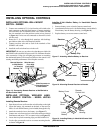
PRE-INSTALLATION
PREPARATION
LOCATION AND SPACE REQUIREMENTS
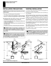
Determine the safest and most effi cient location for your DESA
direct-vent fi replace. Make sure that rafters and wall studs are not
in the way of the venting system. Coose a location where the heat
output is not affected by drafts, air conditioning ducts, windows or
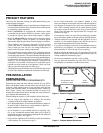
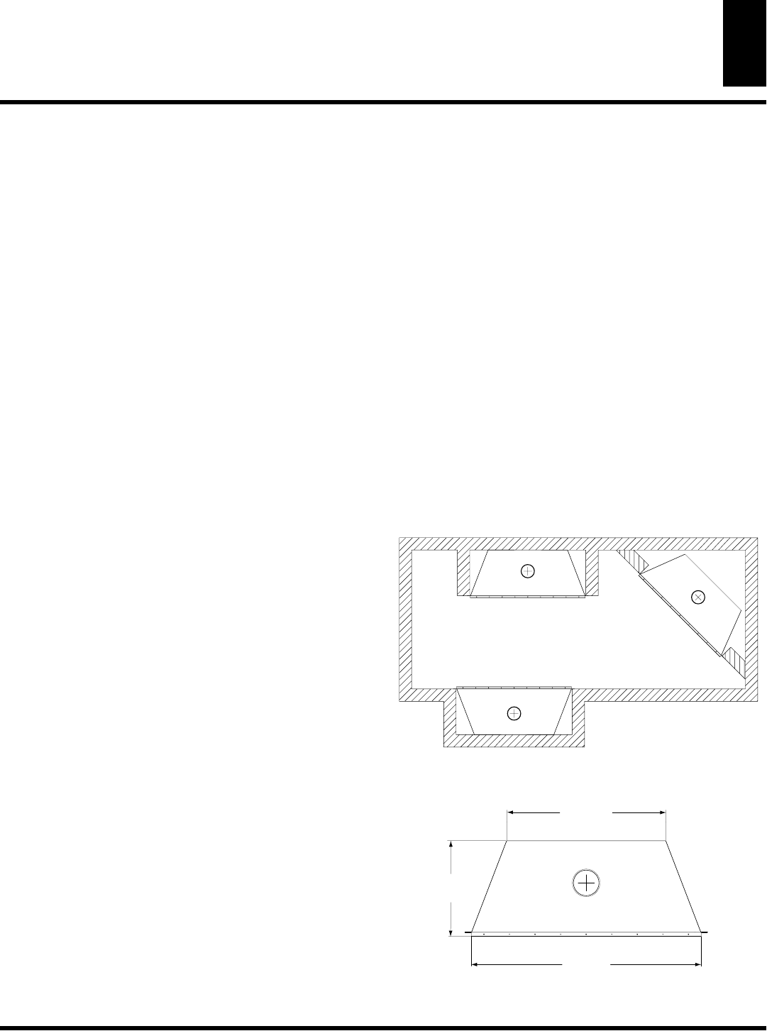
doors. Figure 2 shows some common locations. Be aware of all
restrictions and precautions before deciding the exact location for
your fi replace and termination cap.
When deciding the location of your fi replace, follow these rules:
• Do not connect this fi replace to a chimney fl ue servicing
a separate solid-fuel burning fi replace or appliance.
• Do to high temperatures, do not locate this fi replace in high traf-
fi c areas, windy or drafty areas, or near furniture or draperies.
• Proper clearances must be maintained.
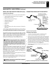
• If your fi replace is to be installed directly on carpeting, vinyl
tile, or any combustible material other than wood, it must be
installed on a metal or wood panel exttending the full width and
depth of the fi replace. See Figure 3.
• Only trim kits supplied by DESA shall be used in the installation
of this fi replace, see
Accessories
, page 33.
• Do not install aftermarket vent dampers. Manual or Auto
matic vent dampers are not approved for use with this appliance.
• Your fi replace is designed to be used in zero clearance installa-
tions. Wall or framing material can be placed directly against
any exterior surface on the back, sides, or top of your fi replace,
except when clearances are required from fl ue vent pipe. See
Clearances
on page 5.
• If recessed into a wall, you can avoid extra framing by position-
ing your fi replace against an already existing framing member.
• A hearth extension is not required with this appliance. If one is
installed, it is for austhetic purposes only and does not have to
meet standard requirements for hearth extensions.
• If you plan on installing a television or entertainment center re-
cessed above your fi replace, it is recommended that you main-
tain a minimum 18” above the top of louver opening.
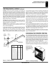
• When locating the termination cap, it is important to observe the
minimum vent height and clearances required under code, see
Venting Installation Instructions
, page 7.
• Do not recess termination cap into a wall or siding.
• You may paint the termination cap with 450°F (232°C) heat-
resistant paint to coordinate with the exterior fi nish.
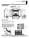
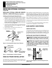
Through exterior wall
enclosed in a chase
Corner
Installation
Flush with a wall
Figure 2 - Common Fireplace Locations
Figure 3 - Fireplace Bottom Dimensions
36"
(914 mm)
15"
(381 mm)
25"
(635 mm)