


Special offers from our partners!

Find Replacement BBQ Parts for 20,308 Models. Repair your BBQ today.
18
106573
DIRECT-VENT GAS FIREPLACE
EVDDVF36PN and EVDDVF36STN
®
INSTALLATION
Continued
WARNING: All gas piping
and connections must be tested
for leaks after the installation is
completed.
After ensuring that the gas valve
is open, apply a soap and water
solution to all connections and
joints. If bubbles appear, leaks
can be detected and corrected.
Do not use an open flame for leak
testing and do not operate any
appliance if a leak is detected.
WARNING: Improper installa-
tion, adjustment, alteration, ser-
vice, or maintenance can cause
injury or property damage. Refer
to this manual. For assistance or
additional information, consult a
qualified installer, service
agency, or gas supplier.
GAS RATING
TYPE OF GAS NATURAL
Max. Input Rating: 30,000 Btu/hr
Orifice Size
(0-4,500 Ft.): 7/64"
Manifold Pressure: 3.5 in. WC
**Minimum Supply
Pressure: 4.5 in. WC
**Maximum Supply
Pressure: 10.5 in. WC
** For the purpose of input adjustment.
GAS SUPPLY TESTING
Note:
This section is intended as a guide for
qualified service technicians installing gas
to the appliance.
CAUTION: Do not connect
appliance before pressure test-
ing gas piping. Damage to the
gas valve may result and an un-
safe condition may be caused.
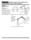
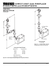
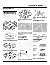
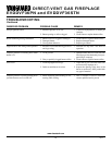
The gas control valve is secured underneath
the firebox with two brackets fastened to the
firebox bottom. Two pressure taps are pro-
vided on the gas control valve for a pressure
gauge connection (see Figure 41).
Equipment
Shutoff
Valve
Flexible Gas Line
Do NOT Kink
1/2" NPT
Incoming
Gas Line
Inlet
Pressure
Tap
Outlet
Pressure
Tap
Note:
1) Wire Connections
Not Shown for Clarity
2) * 1/8" NPT Plugged
Tapping
Figure 41 - Connecting Flexible Gas Line to Electronic Valve
Red Surface Indicates
For Propane/LP Use Only
INSTALLING LOG SET
Before proceeding, make sure the gas con-
trol valve is in the “OFF” position. Logs
have been packaged separately to prevent
damage to glass or refractory.
1. Remove top and bottom louvers by si-
multaneously pulling both top end
spring latches towards the center of the
appliance until they are disengaged from
locating holes. Repeat for bottom end
spring latches and pull outward. Reverse
procedure to install louvers back.
2. Remove the screen rod by sliding
spring clip on one end toward the cen-
ter. Slide rod into screen rod hole until
other end of rod is free. Remove rod.
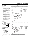
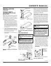
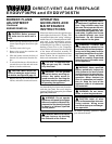
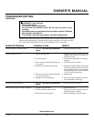
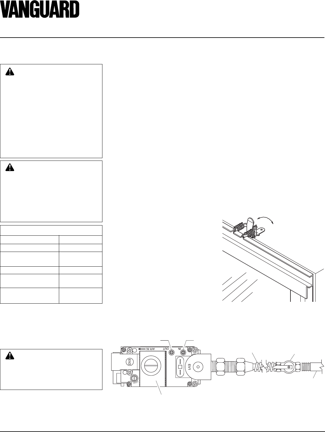
3. To open the glass door, open the pairs
of latches located on the top and bottom
of the firebox (see Figure 42).
Note:
Use
caution when opening these latches.
4. Carefully open the door. The glass door
is mounted to the firebox with 5 screws.
5. To remove the logs from the shrink
wrap, carefully cut the plastic around
the perimeter of the log. Do not try to
remove the logs from the package with-
out first cutting the plastic.
6. Figure 43, page 19 shows the log set.
Logs “A” have the knot at the end of
the log. Logs “B” have the knot at the
middle of the log. Twigs “C” have the
shape of a “Y”. Twigs “D” have the
shape of bent twigs. Twig “E” is a
straight twig which is placed across the
top of Logs “B”.
7. Figure 44, page 19, shows the top view
of the burner and grate.
Open
Close
Figure 42 - Removing Glass Door
8. Place logs “A” as shown in Figure 45,
page 19.
9. Place logs “B” as shown in Figure 46,
page 19. Lift the end of log “A” that will
be propped up and place log “B” under
it. At the same time, the other side of
log “B” is placed over the other log “A”.
Repeat procedure for the other log “B”.
10. Take twigs “C” (shaped like a “Y”)
and place them as shown in Figure 47,
page 19.
11. Take twigs “D” (bent twig) and place
them as shown in Figure 47, page 19.
12. Place twig “E” across the top of logs
“B” a shown in Figure 47, page 19.
13. When finished installing the logs, close
the glass doors while making certain that
the safety door switch is fully depressed
by the door frame before securing the
four (4) spring loaded latches.
14. Replace the louvers in reverse order
with the grilles pointing in the down
position.