


Special offers from our partners!

Find Replacement BBQ Parts for 20,308 Models. Repair your BBQ today.

13
106573
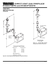
OWNER’S MANUAL
VENTING
INSTALLATION
Continued
Continued
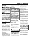
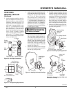
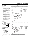
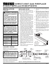
Figure 26 - Cathedral Ceiling Support
Box Installation
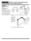
Non-hardening Mastic under all
edges of support box before nailing
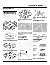
Figure 27 - Installed Cathedral Ceiling
Support Box
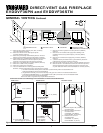
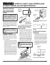
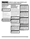
Vertical Termination Configurations
Figures 28 through 31 show four different configurations for vertical termination. All
connections must be sealed with high temperature silicone sealant as specified in the second
warning statement on page 7.
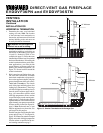
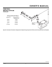
Venting with Two 90° Elbows
Vertical (V) Horizontal (H
1
) +
Horizontal (H
2
)
5' min. 2' max.
6' min. 4' max.
7' min. 6' max.
8' min. 8' max.
20' max. 8' max.
Figure 28 - Vertical Rigid Venting Configuration Using Two 90° Elbows with Two
Horizontal Runs
3. Lower the support box through the hole
in the roof until the bottom of the box
extends at least 2" below the ceiling
(see Figure 26). Align the support box
vertically and horizontally using a level.
Temporarily tack the support box in
place through the inside walls and into
the roof sheathing.
4. Using tin snips, cut the support box from
the top corners down to the roofline and
fold the resulting flaps over the roof
sheathing (see Figure 27). Apply a bead
of non-hardening mastic around the top
edges of the support box to make a seal
between the box and the roof. Nail in
place with roofing nails. Remove any
combustible material that might be in-
side of the support box.
5. Complete the cathedral ceiling instal-
lation by following the same proce-
dures outlined in steps 2 through 7 for
Flat Ceiling Installation, page 12
.
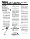
Venting with One 90° Elbow
Vertical (V) Horizontal (H)
5' min. 2' max.
6' min. 4' max.
7' min. 6' max.
8' min. 8' max.
20' max. 8' max.
Figure 29 - Vertical Rigid Venting Configuration Using One 90° Elbow
Cut hole 1/8" larger than support
box when projected onto roofline
2" minimum below
finished ceiling
Cathedral ceiling
support box
Level
45° Starter Elbow
Required
45° Starter Elbow
Required