


Special offers from our partners!

Find Replacement BBQ Parts for 20,308 Models. Repair your BBQ today.
17
106573
OWNER’S MANUAL
INSTALLATION
Continued
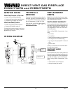
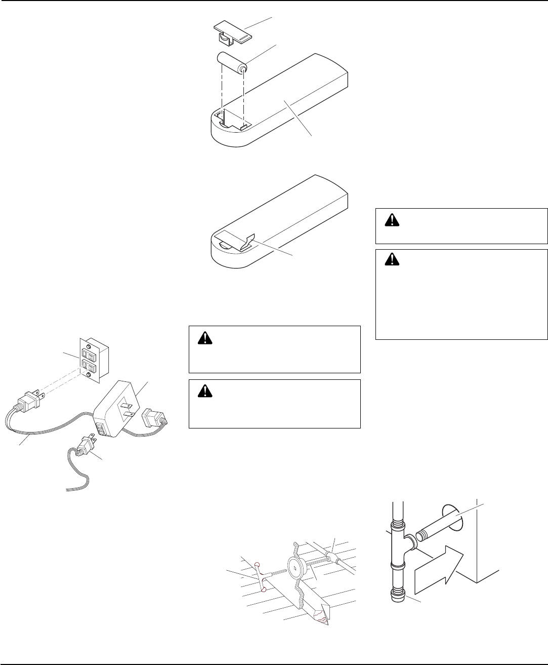
GAS LINE HOOK-UP
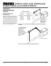
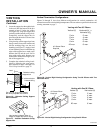
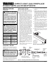
Figure 39 - Typical Exterior Wall Gas
Shutoff Installation
WARNING: Gas line hookup
should be done by your gas sup-
plier or a qualified service person.
WARNING: Before you pro-
ceed, make sure your gas supply
is OFF.
A equipment shutoff valve has been in-
cluded in the appliance’s gas supply system.
You may consider installing an extra gas
shutoff valve outside the appliance’s enclo-
sure (check with local codes) where it can be
accessed more conveniently with a key
through a wall as shown in Figure 39.
Key
Extension
Shutoff Valve
CAUTION: Compounds used
on threaded joints of gas piping
shall be resistant to the action of
Liquefied Petroleum (LP or pro-
pane), and should be applied
lightly to ensure excess sealant
does not enter the gas line.
CAUTION: Do not kink flex-
ible gas line.
Route a 1/2” NPT black iron gas line to-
wards the appliance coming in from the left.
It is recommended to route the pipe between
the stand of the firebox and the surround of
the fireplace (see Figure 40).
IMPORTANT:
The appliance and its indi-
vidual shutoff valve must be disconnected
from the gas supply piping system during
any pressure testing of that system at test
pressures in excess of 1/2 psig. (3.5 kPa).
The appliance must be isolated from the gas
supply piping system by closing its indi-
vidual equipment shutoff valve during any
pressure testing of the gas supply piping
system at test pressures equal to or less than
1/2 psig. (3.5 kPa).
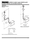
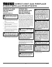
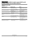
1. Install a sediment trap between the in-
coming gas line and the gas control
valve (see Figure 40). The sediment
trap should extend down the center of
the pipe. Refer to your local codes.
2. Prepare incoming gas line and check
with local codes regarding the use of
teflon tape. Complete your gas line in-
stallation by connecting incoming gas
line with flexible gas line. Secure
tightly with a wrench, but Do NOT
Overtighten.
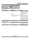
OPTIONAL REMOTE
CONTROL INSTALLATION
(Model WRC)
Note:
If using optional wireless hand-held
remote control, the wall switch must be in
the ON position to be operational. The re-
mote control then becomes the switching
mechanism for fireplace operation.
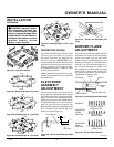
1. The WRC model receiver does not re-
quire a battery. The receiver can be in-
stalled by first plugging the short ex-
tension cord into the fireplace junction
box. Then plug the receiver unit into
the extension cord. Finally plug the ig-
nition module plug into the receiver unit
(see Figure 37).
2. Activate the remote handset battery by
removing the insulating tab on the back
of the handset (see Figure 38). The bat-
tery is included pre-installed.
3. Once the battery is activated the unit is
ready to use.
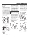
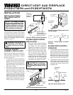
Figure 37 - Installing the WRC Remote
Receiver
Junction
Box
Remote
Control
Receiver
Extension
Cord
Ignition
Module Plug
Figure 38 - Installing Battery into Back of
Handset
Pull to Remove
Insulation Tab
Battery Cover
12 Volt Battery
Back of Handset
Continued
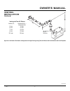
Back Wall
Of Appliance
Incoming 1/2"
Gas Line
Permitted by
Local Codes
Sediment Trap (Not Supplied)
Figure 40 - Sediment Trap