


Special offers from our partners!

Find Replacement BBQ Parts for 20,308 Models. Repair your BBQ today.
16
106573
DIRECT-VENT GAS FIREPLACE
EVDDVF36PN and EVDDVF36STN
®
INSTALLATION
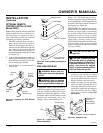
INSTALLING OPTIONAL
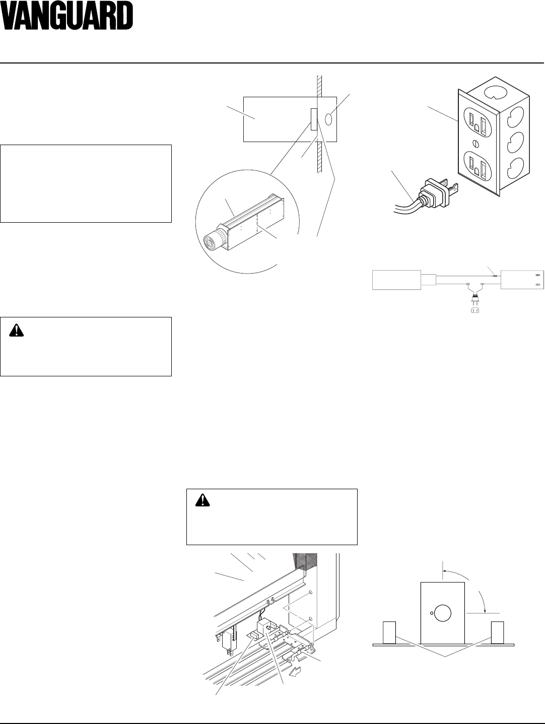
WALL MOUNT SWITCH
GWMS2
NOTICE: The GWMS2 includes
25' of wire for installation. Your
fireplace includes 15' of wire for
accessory installation. Choose the
length that best fits your needs
when installing this accessory.
The installation of a wall switch allows you
to activate the gas control valve and turn
the fireplace on and off. The wall switch is
to be connected to the incoming 120 volt
regular household wiring that supplies elec-
tricity to the fireplace. Refer to wiring
diagram on page 22.
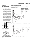
For Optional
Fan Kit
From Blower
Assembly
CAUTION: Due to high tem-
peratures, make sure no wires
are touching the bottom of the
firebox.
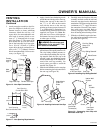
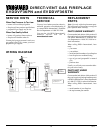
OPTIONAL BLOWER
ASSEMBLY INSTALLATION
Before blower assembly can be operated, it
must be properly connected to a standard
120 VAC power source. Refer to Wiring
Diagram on page 22.
1. To remove lower louver, pull both top
spring latches toward the center of the
appliance at the same time until they
are disengaged from the locating holes.
Repeat for bottom spring latches and
pull louver outward.
2. Place blower assembly so it rests flush
against the inside wall on the flue exit
side of the firebox (see Figure 32).
There are four magnets on the bottom
of the blower assembly that will keep
the blower in place on firebox bottom.
Note:
If the blower kit is not installed
flush against the inside side wall of the
fireplace, the circulating air from the
blower system will not flow properly.
WARNING: Disconnect all
electrical power to the fireplace.
Be careful of burrs and sharp
edges.
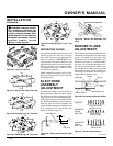
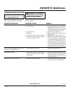
BLOWER SPEED CONTROL
INSTALLATION
1. Place speed control switch assembly on
the bottom of the inside of the firebox
(see Figure 33). The assembly is
equipped with magnets on the left and
right to properly anchor it to the firebox.
2. Plug blower with speed control assem-
bly into a power source. Keep hands
clear of fan when running.
Note:
An
outlet box with two receptacles has been
supplied for your convenience, located
on the lower left side of the appliance
(see Figure 34). An optional remote
control may be installed at any time.
Figure 32 - Blower Assembly Placement
Blower
Assembly
Blower Center to
Firebox Bottom
Center Along Inside
Wall by Flue Exit
Peninsula
or See-Thru
Fireplace
Installed
Flue
Exit
Inside
Wall
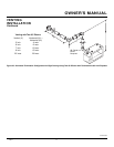
BLOWER SPEED CONTROL
OPERATION
1. To operate blower, turn the blower speed
control knob clockwise to the “on” po-
sition (see Figure 36). This will be the
highest blower speed. Continue turning
knob clockwise to reduce blower speed.
Turn knob only within the specified
range (1/4 revolution, see Figure 36).
2. To turn blower off, turn blower speed
control knob counter-clockwise until it
clicks into the “off” position. You must
turn until knob clicks for the unit to be
completely off.
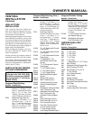
Figure 34 - Connecting Blower Accessory
to Power Supply
Figure 33 - Blower Speed Control Location
Glass
Speed Control
Spring
Latch
BLOWER
SPEED
CONTROL
BLOWER
ASSEMBLY
BLK (16 ga.)
BLK (16 ga.)
Wire Connectors
3 Places
Figure 35 - Wiring Diagram for Blower
Assembly
Magnet
High Speed
ON/OFF
Low
Speed
Magnets
1/4 Revolution
Figure 36 - Blower Speed Control