


Special offers from our partners!

Find Replacement BBQ Parts for 20,308 Models. Repair your BBQ today.
12
106573
DIRECT-VENT GAS FIREPLACE
EVDDVF36PN and EVDDVF36STN
®
4. Connect a section of pipe and extend
up through the hole.
Note:
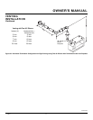
If an offset is needed to avoid
obstructions, you must support the vent
pipe every 3 feet. Use wall straps for
this purpose (see Figure 24). Whenever
possible, use 45° elbows instead of 90°
elbows. The 45° elbow offers less re-
striction to the flow of the flue gases
and intake air.
5. Place the flashing over the pipe
section(s) extending through the roof.
Secure the base of the flashing to the
roof and framing with roofing nails. Be
sure roofing material overlaps the top
edge of the flashing as shown in Figure
24. There must be a 1" clearance from
the vent pipe to combustible materials.
6. Continue to add pipe sections until the
height of the vent cap meets the mini-
mum building code requirements de-
scribed in Figure 13 on page 6.
Note
:
You must increase vent height for steep
roof pitches. Nearby trees, adjoining
rooflines, steep pitched roofs, and other
similar factors may cause poor draft or
down-drafting in high winds. Increasing
the vent height may solve this problem.
7. Twist-lock the vent cap onto the last
section of vent pipe and seal with high
temperature silicone sealant as speci-
fied in the second warning statement
on page 7.
Note:
If the vent pipe passes through any
occupied areas above the first floor, including
storage spaces and closets, you must enclose
pipe. You may frame and sheetrock the enclo-
sure with standard construction material. Make
sure and meet the minimum allowable clear-
ances to combustibles. Do not fill any of the
required air spaces with insulation.
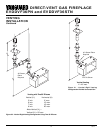
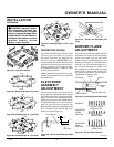
Cathedral Ceiling Installation
1. Remove shingles or other roof cover-
ing as necessary to cut the rectangular
hole for the support box. Mark the out-
line of the cathedral ceiling support box
on the roof sheathing using the locat-
ing hole as a center point.
2. Cut the hole 1/8" larger than the sup-
port box outline (see Figure 26, page 13).
1. Determine the route your vertical vent-
ing will take. If ceiling joists, roof
rafters, or other framing will obstruct
the venting system, consider an offset
(see Figure 24) to avoid cutting
loadbearing members.
Note:
Pay spe-
cial attention to these installation in-
structions for required clearances (air
space) to combustibles when passing
through ceilings, walls, roofs, enclo-
sures, attic rafters, etc. Do not pack air
spaces with insulation. Also note maxi-
mum vertical rise of the venting sys-
tem and any maximum horizontal off-
set limitations. Offsets must fall within
the parameters shown in Figure 13 on
page 6.
2. Set the fireplace in desired location.
Drop a plumb line down from the ceil-
ing to the position of the fireplace exit
flue. Mark the center point where the
vent will penetrate the ceiling. Drill a
small locating hole at this point.
Drop a plumb line from the inside of
the roof to the locating hole in the ceil-
ing. Mark the center point where the
vent will penetrate the roof. Drill a
small locating hole at this point.
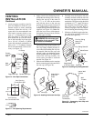
Flat Ceiling Installation
1. Cut a 10" square hole in the ceiling us-
ing the locating hole as a center point.
The opening should be framed to
10"x10" (254mm x 254mm) inside di-
mensions, as shown in Figure 17 on
page 9 using framing lumber the same
size as the ceiling joists. If the area
above the ceiling is an insulated ceil-
ing or a room, nail firestop from the
top side. This prevents loose insulation
from falling into the required clearance
space. Otherwise, install firestop below
the framed hole. The firestop should be
installed with no less than three nails
per side (see Figure 25).
2. Assemble the desired lengths of pipe
and elbows necessary to reach from the
fireplace flue up through the firestop.
All connections must be sealed with
high temperature silicone sealant as
specified in the second warning state-
ment on page 7. Be sure all pipe and
elbow connections are fully twist-
locked (see Figure 16, page 9).
3. Cut a hole in the roof using the locating
hole as a center point. (Cover any ex-
posed open vent pipes before cutting
hole in roof.) The 10"x10" hole must
be measured on the horizontal; actual
length may be larger depending on the
pitch of the roof. There must be a 1"
clearance from the vent pipe to combus-
tible materials. Frame the opening as
shown in Figure 17 on page 9.
VENTING
INSTALLATION
Continued
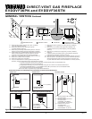
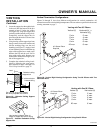
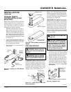
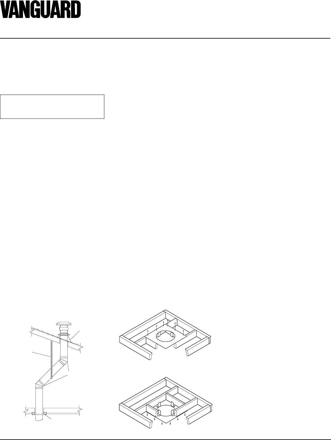
Figure 24 - Offset with Wall Strap and 45°
45° Elbow
Wall Strap
Roof
Flashing
Ceiling Firestop
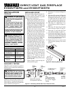
Figure 25 - Installing Firestop
If area above is not a room, install
firestop below framed hole.
If area above is a room, install firestop
above framed hole.
INSTALLATION FOR
VERTICAL TERMINATION
NOTICE: Use rigid pipe only. Flex
venting is not to be used with a
vertical termination.