


Special offers from our partners!

Find Replacement BBQ Parts for 20,308 Models. Repair your BBQ today.

111410-01C
For more information, visit www.desatech.com
For more information, visit www.desatech.com
9
9
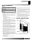
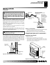
IMPORTANT:
Noncombustible materials such as brick, tile, etc.
may overlap the front facing, but should never cover any necessary
openings like louvered slots.
WARNING: Do not allow noncombustible materials
to cover any necessary openings like louvered slots.
WARNING: Use only noncombustible mortar or
adhesives when overlapping the front facing with
noncombustible facing material.
WARNING: Never modify or cover the louvered
slots on the front of the firebox.
INSTALLATION
Continued
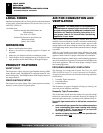
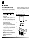
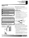
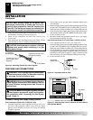
13"
16"
19"
21"
2
1
/2"
6"
8"
10"
Minimum Non-
Combustible
Material
Mantel Shelf
Note:
All vertical
measurements are from
top of fireplace opening
to bottom of mantel shelf.
NOTICE: If your installation does not meet the minimum
clearances shown, you must do one of the following:
• raise the mantel to an acceptable height
• remove the mantel
NOTICE: Surface temperatures of adjacent walls and
mantels become hot during operation. Walls and
mantels above the firebox may become hot to the
touch. If installed properly, these temperatures meet
the requirement of the national product standard.
Follow all minimum clearances shown in this manual.
Mantel Clearances for Built-In Installation
If placing mantel above built-in fireplace, you must meet minimum
clearance between mantel shelf and top of fireplace opening.
Figure 9 - Minimum Mantel Clearances for Built-In Installation
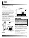
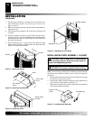
REMOVING BRICK LINER RETAINER
1. Using Phillips screw driver, remove 2 screws attaching brick
liner retainers to vertical sides.
2. Remove brick liner retainers and discard. Replace 2 screws into
vertical sides.
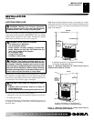
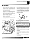
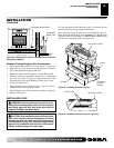
ASSEMBLING TRIM
(Trim shipped with mantel)
1. Remove packaging from three pieces of trim.
2. Locate two adjusting plates with set screws, and two shims in
the hardware packet.
3. Align shim under adjusting plate as shown in Figure 10.
4. Slide one end of adjusting plate/shim in slot on mitered edge
of top trim (see Figure 10).
5. Slide other end of adjusting plate/shim in slot on mitered edge
of side trim (see Figure 10).
6. While firmly holding edges of trim together, tighten both set
screws on the adjusting plate with slotted screwdriver.
7. Repeat steps 1 through 6 for other corner.
8. Set brass assembly aside for later installation.
Figure 10 - Assembling Trim
Top Trim
Side Trim
Mitered Edge
Shim
Set Screws
Adjusting
Plate
Slot
Slot
INSTALLATION
Built-In Fireplace Installation (Cont.)
Removing Brick Liner Retainer
Assembling Trim
Optional Mantel Installation
OPTIONAL MANTEL INSTALLATION
Note:
Refer to instructions provided with the mantel for assembly
instructions. Refer to instructions below for system installation. If
using blower accessory (see Accessories, page 29), see installation
instructions on pages 11 and 12.
1
.
Choose location for fireplace and install gas supply line.
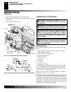
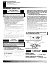
2. Remove screen from fireplace by removing screws in each
end of screen rod (see Figure 11, page 10). Hold screen rod
cover while removing five hex head screws underneath hood
(see Figure 12, page 10). Carefully lift and pull out hood (see
Figure 13, page 10).
3. Assemble trim kit. See Assembling Trim, above.
4. Place trim on the shoulder screws located on the side and top
of the fireplace. Firmly snap the trim over the shoulder screws
on fireplace (see Figure 14, page 10).
5. Place mantel base close to wall in desired fireplace location.
6. Install gas line. See Connecting To Gas Supply, pages 12 and 13.